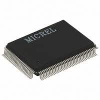
KS8997 Micrel Inc, KS8997 Datasheet - Page 21

KS8997
Manufacturer Part Number
KS8997
Description
IC SWITCH 10/100 8PORT 128PQFP
Manufacturer
Micrel Inc
Specifications of KS8997
Applications
*
Mounting Type
Surface Mount
Package / Case
128-MQFP, 128-PQFP
Fiber Support
No
Integrated Led Drivers
Yes
Phy/transceiver Interface
MII
Power Supply Type
Analog/Digital
Package Type
PQFP
Data Rate (typ)
10/100Mbps
Vlan Support
Yes
Operating Temperature (max)
70C
Operating Temperature (min)
0C
Pin Count
128
Mounting
Surface Mount
Jtag Support
No
Operating Temperature Classification
Commercial
Lead Free Status / RoHS Status
Contains lead / RoHS non-compliant
Available stocks
Company
Part Number
Manufacturer
Quantity
Price
Company:
Part Number:
KS8997
Manufacturer:
KENDIN
Quantity:
885
Part Number:
KS8997
Manufacturer:
REALTEK/瑞昱
Quantity:
20 000
EEPROM Operation
The EEPROM interface utilizes 2 pins that provide a clock and a serial data path. As part of the initialization sequence, the
KS8997 reads the contents of the EEPROM and loads the values into the appropriate registers. Note that the first two bytes
in the EEPROM must be “55” and “99” respectively for the loading to occur properly. If these first two values are not correct,
all other data will be ignored.
Data start and stop conditions are signaled on the data line as a state transition during clock high time. A high to low transition
indicates start of data and a low to high transition indicates a stop condition. The actual data that traverses the serial line
changes during the clock low time.
The KS8997 EEPROM interface is compatible with the Atmel AT24C01A part. Further timing and data sequences can be found
in the Atmel AT24C01A specification.
EEPROM Memory Map
August 2003
KS8997
Address
0
1
General Control Register
2
2
2
2
Priority Classification Control - 802.1p tag field
3
3
3
3
3
3
3
3
Port 1 Control Register
4
4
4
Name
7-0
7-0
7-4
3-2
1
0
7
6
5
4
3
2
1
0
7-6
5
4
Description
Signature byte 1. Value = “55”
Signature byte 2. Value = “99”
Reserved - set to zero
Priority control scheme (all ports)
00 = Transmit all high priority before any low priority
01= Transmit high and low priority at a 10:1 ratio
10 = Transmit high and low priority at a 5:1 ratio
11 = Transmit high and low priority at a 2:1 ratio
Priority buffer reserve for high priority traffic
1 = Reserve 6KB of buffer space for high priority
0 = None reserved
VLAN enforcement
1 = All unicast frames adhere to VLAN configuration
0 = Unicast frames ignore VLAN configuration
1 = State “111” is high priority
0 = State “111” is low priority
1 = State “110” is high priority
0 = State “110” is low priority
1 = State “101” is high priority
0 = State “101” is low priority
1 = State “100” is high priority
0 = State “100” is low priority
1 = State “011” is high priority
0 = State “011” is low priority
1 = State “010” is high priority
0 = State “010” is low priority
1 = State “001” is high priority
0 = State “001” is low priority
1 = State “000” is high priority
0 = State “000” is low priority
Reserved - set to zero
TOS priority classification enable for port 1
1 = Enable
0 = Disable
802.1p priority classification enable for port 1
1 = Enable
0 = Disable
21
Default
(chip) Value
0x55
0x99
0000
00
0
0
1
1
1
1
0
0
0
0
00
0
0
KS8997
Micrel


