ACPL-M43T-500 Avago Technologies US Inc., ACPL-M43T-500 Datasheet
ACPL-M43T-500
Specifications of ACPL-M43T-500


Related parts for ACPL-M43T-500


ACPL-M43T-500 Summary of contents
Page 1
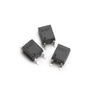
... RoHS 6 fully compliant options available; -xxxE denotes a lead-free product Description The ACPL-M43T is a single channel, high temperature, high CMR, high speed digital optocoupler in a five lead minia- ture footprint specifically used in the automotive applica- tions. The SO-5 JEDEC registered (MO-155) package outline does not require “ ...
Page 2
... To order, choose a part number from the part number column and combine with the desired option from the option column to form an order entry. Example 1: ACPL-M43T-500E to order product of Mini-flat Surface Mount 5-pin package in Tape and Reel packaging with RoHS compliant. Example 2: ACPL-M43T to order product of Mini-flat Surface Mount 5-pin package in tube packaging and non RoHS compliant. ...
Page 3
... Recommended reflow condition as per JEDEC Standard, J-STD-020 (latest revision). Note: Non-halide flux should be used. Regulatory Information The ACPL-M43T is approved by the following organizations: UL Approved under UL 1577, component recognition pro- gram 4000 V ISO RMS CSA Approved under CSA Component Acceptance Notice #5. IEC/EN/DIN EN 60747-5-2 Insulation Characteristics* Description Installation classification per DIN VDE 0110/1 ...
Page 4
Absolute Maximum Ratings Parameter Storage Temperature Operating Temperature Lead Soldering Cycle Temperature Time Average Forward Input Current Peak Forward Input Current (50% duty cycle, 1ms pulse width) Peak Transient Input Current (<= 1us pulse width, 300ps) Reversed Input Voltage Input ...
Page 5
Electrical Specifications (DC) Over recommended operating T = -40°C to 125°C, unless otherwise specified. A Parameter Sym. Min. Current Transfer CTR 32 Ratio 20 Logic Low V OL Output Voltage Logic High I OH Output Current Logic Low I CCL ...
Page 6
Switching Specifications (AC) Over recommended operating (T = -40°C to 125°C Parameter Symbol Min Propagation Delay T 0.08 PHL Time to Logic Low 0.06 at Output Propagation Delay T 0.15 PLH Time to Logic High 0.03 at Output ...
Page 7
25° OUTPUT VOLTAGE - V O Figure 1. DC and Pulsed Transfer Characteristics. 100. 10. − 1.00 ...
Page 8
Vcc=3V I =10mA, T =25° Vcc=5V C =15pF 2.0 L 1.5 T PLH 1.0 0 LOAD RESISTANCE - kΩ L Figure 7. Propagation Delay Time vs Load ...
Page 9
1 PHL PLH Figure 13. Switching Test Circuit 1500 V 90% 90 10% 10 ...