HCPL-5300#100 Avago Technologies US Inc., HCPL-5300#100 Datasheet
HCPL-5300#100
Specifications of HCPL-5300#100
Available stocks


Related parts for HCPL-5300#100


HCPL-5300#100 Summary of contents
Page 1
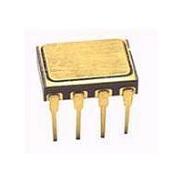
... Interface Hermetically Sealed Optocouplers Data Sheet HCPL-5300, HCPL-5301, HCPL-530K, 5962-96852 Description The HCPL-530X devices consist of a GaAsP LED optically coupled to an integrated high gain photo detector in a hermetically sealed package. The products are capable of operation and storage over the full military temperature ...
Page 2
... Outline Drawing 9.40 (0.370) 9.91 (0.390) 0.76 (0.030) 1.27 (0.050) 0.51 (0.020) MIN. 2.29 (0.090) 2.79 (0.110) NOTE: DIMENSIONS IN MILLIMETERS (INCHES). 2 HCPL-5300 HCPL-5301 HCPL-530K Gold Plate Option #200 Option #100 Option #300 5962- 9685201HPX 9685201HPC 9685201HPA 9685201HYC 9685201HYA 9685201HXA 5962- 9685201KPX ...
Page 3
Device Marking Avago DESIGNATOR A QYYWWZ XXXXXX Avago P/N XXXXXXX DSCC SMD* DSCC SMD* XXX XXX PIN ONE/ 50434 ESD IDENT * QUALIFIED PARTS ONLY ;; ;; ; ; ; Hermetic Optocoupler Options Option Description 100 Surface mountable hermetic optocoupler ...
Page 4
Absolute Maximum Ratings Parameter Storage Temperature Operating Temperature Junction Temperature Lead Solder Temperature Average Input Current Peak Input Current (50% duty cycle pulse width) Peak Transient Input Current ( 1 s pulse width, 300 pps) Reverse Input Voltage ...
Page 5
Electrical Specifications Over recommended operating conditions ( 0.8 V) unless otherwise specified. F(OFF) Group A Parameter Symbol Subgroups Current Transfer CTR Ratio Low Level Output Current Low ...
Page 6
Switching Specifications ( External) L Over recommended operating conditions 0.8 V) unless otherwise specified. F(OFF) Group A Parameter Symbol Subgrps. Propagation t 9, 10, 11 PHL Delay Time to Low Output ...
Page 7
Switching Specifications (R = Internal Pull-up) L Over recommended operating conditions 0.8 V) unless otherwise specified. F(OFF) Group A Parameter Symbol Subgrps. Propagation t 9, 10, 11 PHL Delay Time to Low Output Level ...
Page 8
... Without a detector shield, the dominant cause of optocoupler CMR failure is capacitive coupling from the input side of the optocoupler, through the package, to the detector IC as shown in Figure 14. The HCPL-530X improves CMR performance by using a detector IC with an optically transparent Faraday shield, which diverts the capacitively coupled current away from the sensitive IC circuitry ...
Page 9
... PLH Figure 24. The maximum dead time is also equivalent to the difference between the maximum and minimum propagation delay difference specifications. The maximum dead time (due to the optocouplers) for the HCPL-530X is 670 ns (= 500 ns - (-170 ns)) over an operating temperature range of - +125 C. ) propagation delay specifi- PLH - t ...
Page 10
125 °C 25 °C -55 ° – FORWARD LED CURRENT – Figure 1. Typical transfer characteristics 1000 T = 25°C A ...
Page 11
SHIELD V FF – 1000 V CM Figure 6. CMR test circuit. Typical CMR waveform 600 ...
Page 12
100 pF PLH PHL T = 25°C 400 A 300 200 100 – FORWARD LED CURRENT – Figure ...
Page 13
I I TOTAL* k CLEDP C 2 LED02 LEDP F 300 C LED01 I CLED01 LEDN 4 5 SHIELD * THE ARROWS INDICATE THE DIRECTION OF CURRENT FLOW FOR +dV /dt ...
Page 14
... PROPAGATION DELAY DIFFERENCE NOTE: THE PROPAGATION DELAYS USED TO CALCULATE PDD ARE TAKEN AT EQUAL TEMPERATURES. Figure 23. Minimum LED skew for zero dead time 14 V CC1 0.1 µ OUT1 HCPL-5300 V CC2 0.1 µF HCPL-5300 20 k HCPL-5300 V OUT2 HCPL-5300 HCPL-5300 Q1 OFF PHL MIN. IPM Q1 Q2 +HV M -HV ...
Page 15
I LED1 OUT1 V OUT2 Q2 OFF I LED2 t PLH MIN. t PLH MAX. t PDD* PHL MAX. MIN. t PHL MAX. MAX. DEAD TIME MAXIMUM DEAD TIME = ( PLH MAX. PLH MIN. ...
Page 16
For product information and a complete list of distributors, please go to our website: Avago, Avago Technologies, and the A logo are trademarks of Avago Technologies Limited in the United States and other countries. Data subject to change. Copyright © ...