TLP351(F) Toshiba, TLP351(F) Datasheet - Page 3
TLP351(F)
Manufacturer Part Number
TLP351(F)
Description
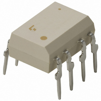
IC PHOTOCOUPLER IRED 8-DIP
Manufacturer
Toshiba
Specifications of TLP351(F)
Voltage - Isolation
3750Vrms
Number Of Channels
1, Unidirectional
Current - Output / Channel
600mA
Current - Dc Forward (if)
20mA
Input Type
DC
Output Type
Push-Pull, Totem-Pole
Mounting Type
Through Hole
Package / Case
8-DIP (0.300", 7.62mm)
Configuration
1 Channel
Maximum Forward Diode Voltage
1.7 V
Maximum Reverse Diode Voltage
5 V
Maximum Input Diode Current
10 mA
Maximum Operating Temperature
+ 100 C
Minimum Operating Temperature
- 40 C
Isolation Voltage
3750 Vrms
Maximum Continuous Output Current
0.6 A
Maximum Fall Time
50 ns
Maximum Forward Diode Current
20 mA
Maximum Rise Time
50 ns
Minimum Forward Diode Voltage
1.55 V
Output Device
Totem Pole
No. Of Channels
1
Optocoupler Output Type
Gate Drive
Input Current
10mA
Output Voltage
35V
Opto Case Style
DIP
No. Of Pins
8
Operating Temperature Range
-40°C To
Rohs Compliant
Yes
Lead Free Status / RoHS Status
Lead free / RoHS Compliant
Other names
TLP351
TLP351
TLP351F
TLP351
TLP351F
Available stocks
Company
Part Number
Manufacturer
Quantity
Price
Company:

Part Number:
TLP351(F)
Manufacturer:
TOSHIBA
Quantity:
28 000
Part Number:
TLP351(F)
Manufacturer:
TOSHIBA/东芝
Quantity:
20 000


Electrical Characteristics
Isolation Characteristics
Forward voltage
Temperature coefficient of forward
voltage
Input reverse current
Input capacitance
Output current
Output voltage
Supply current
Threshold input current
Threshold input voltage
Supply voltage
*: All typical values are at Ta = 25°C
Note 8: Duration of I
Note 9: This product is more sensitive than the conventional product to static electricity (ESD) because of a lowest
Capacitance input to output
Isolation resistance
Isolation voltage
power consumption design.
General precaution to static electricity (ESD) is necessary for handling this component.
Characteristics
Characteristic
(Note 8)
O
time ≤ 50 μs
“H” Level
“H” Level
“H” Level
“L” Level
“L” Level
“L” Level
L → H
H → L
(Ta = 25°C)
(Ta = −40 to 100°C, unless otherwise specified)
∆V
Symbol
I
I
I
I
V
I
OPH1
OPH2
I
OPL1
OPL2
V
I
V
V
CCH
CCL
F
FLH
V
C
I
FHL
OH
OL
CC
R
/∆Ta
F
T
Symbol
BV
C
R
S
S
S
Circuit
Test
⎯
⎯
⎯
⎯
⎯
⎯
⎯
1
2
3
4
5
6
V = 0,f = 1MHz
V
R.H. ≤ 60%
AC,1 minute
AC,1 second,in oil
DC,1 minute,in oil
I
I
V
V = 0 , f = 1 MHz,Ta = 25°C
V
I
V
I
V
V
V
V
V
S
F
F
F
F
R
CC
CC
CC
CC
O
CC
CC
3
= 5 mA, Ta = 25°C
= 5 mA
= 5 mA
= 0 mA
= 500 V, Ta = 25°C,
= 5 V, Ta = 25°C
open
= 10 to 30 V
= 15 V
= 15 V
= 10 V
= 15 V, V
= 15 V, V
Test Conditions
Test Condition
O
O
> 1 V
< 1 V
⎯
V
V
V
V
I
I
I
V
I
I
O
F
O
F
F
8-6
8-6
6-5
6-5
F
= 5 mA
= 10 mA
= 0 mA
= −100 mA,
= 100 mA,
= 0.8 V
= 4 V
= 10 V
= 2 V
= 10 V
(Note5)
(Note5)
1×10
3750
Min.
⎯
―
―
−0.2
−0.4
Min
0.2
0.4
6.0
0.8
⎯
⎯
⎯
⎯
⎯
10
⎯
⎯
⎯
12
10000
10000
10
Typ.
1.0
―
−0.67
Typ.*
14
1.55
−2.0
−0.4
0.35
0.63
8.5
0.4
1.4
1.3
2.5
45
⎯
⎯
⎯
2007-10-01
Max.
⎯
―
―
―
―
TLP351
Max
1.70
1.0
2.0
2.0
⎯
10
⎯
⎯
⎯
⎯
⎯
⎯
⎯
30
5
V
Unit
Vdc
mV/°C
pF
Ω
rms
Unit
mA
mA
μA
pF
V
A
V
V
V
Related parts for TLP351(F)
Image
Part Number
Description
Manufacturer
Datasheet
Request
R

Part Number:
Description:
TOSHIBA Photocoupler GaAAs IRED + Photo IC
Manufacturer:
Toshiba Semiconductor
Datasheet:

Part Number:
Description:
PHOTOCOUPLER IRED 20MA 8DIP SMD
Manufacturer:
Toshiba
Datasheet:


Part Number:
Description:
Toshiba Semiconductor [TOSHIBA IGBT Module Silicon N Channel IGBT]
Manufacturer:
TOSHIBA Semiconductor CORPORATION
Datasheet:
Part Number:
Description:
TOSHIBA GTR MODULE SILICON NPN TRIPLE DIFFUSED TYPE
Manufacturer:
TOSHIBA Semiconductor CORPORATION
Datasheet:
Part Number:
Description:
TOSHIBA GTR Module Silicon N Channel IGBT
Manufacturer:
TOSHIBA Semiconductor CORPORATION
Datasheet:
Part Number:
Description:
TOSHIBA Intelligent Power Module Silicon N Channel IGBT
Manufacturer:
TOSHIBA Semiconductor CORPORATION
Datasheet:
Part Number:
Description:
TOSHIBA INTELLIGENT POWER MODULE SILICON N CHANNEL LGBT
Manufacturer:
TOSHIBA Semiconductor CORPORATION
Datasheet:
Part Number:
Description:
TOSHIBA IGBT Module Silicon N Channel IGBT
Manufacturer:
TOSHIBA Semiconductor CORPORATION
Datasheet:
Part Number:
Description:
TOSHIBA GTR MODULE SILICON N−CHANNEL IGBT
Manufacturer:
TOSHIBA Semiconductor CORPORATION
Datasheet:
Part Number:
Description:
TOSHIBA Intelligent Power Module Silicon N Channel IGBT
Manufacturer:
TOSHIBA Semiconductor CORPORATION
Datasheet:
Part Number:
Description:
TOSHIBA GTR Module Silicon N Channel IGBT
Manufacturer:
TOSHIBA Semiconductor CORPORATION
Datasheet:
Part Number:
Description:
TOSHIBA INTELLIGENT POWER MODULE
Manufacturer:
TOSHIBA Semiconductor CORPORATION
Datasheet:
Part Number:
Description:
TOSHIBA Intelligent Power Module Silicon N Channel IGBT
Manufacturer:
TOSHIBA Semiconductor CORPORATION
Datasheet:
Part Number:
Description:
TOSHIBA Intelligent Power Module Silicon N Channel IGBT
Manufacturer:
TOSHIBA Semiconductor CORPORATION
Datasheet: