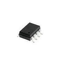
HCPL-3000-500E Avago Technologies US Inc., HCPL-3000-500E Datasheet - Page 4

HCPL-3000-500E
Manufacturer Part Number
HCPL-3000-500E
Description
OPTOCOUPLER BIPOLAR 8-SMD
Manufacturer
Avago Technologies US Inc.
Datasheet
1.HCPL-3000.pdf
(10 pages)
Specifications of HCPL-3000-500E
Output Type
Push-Pull, Totem-Pole
Package / Case
8-SMD Gull Wing
Voltage - Isolation
5000Vrms
Number Of Channels
1, Unidirectional
Current - Output / Channel
500mA
Propagation Delay High - Low @ If
2µs @ 5mA
Current - Dc Forward (if)
20mA
Input Type
DC
Mounting Type
Surface Mount, Gull Wing
Fall Time
1 us
Rise Time
1 us
Configuration
1 Channel
Isolation Voltage
5000 Vrms
Maximum Propagation Delay Time
5 us
Maximum Forward Diode Voltage
1.4 V
Maximum Reverse Diode Voltage
6 V
Maximum Forward Diode Current
20 mA
Maximum Continuous Output Current
0.6 A
Maximum Power Dissipation
550 mW
Maximum Operating Temperature
+ 80 C
Minimum Operating Temperature
- 20 C
Lead Free Status / RoHS Status
Lead free / RoHS Compliant
Absolute Maximum Ratings
Storage Temperature
Operating Temperature
Input
Supply Voltage
Output 1
Output 2
Output Power Dissipation
Total Power Dissipation
Lead Solder Temperature
Recommended Operating Conditions
Power Supply Voltage
Input Current (ON)
Input Current (OFF)
Operating Temperature
*The initial switching threshold is 5 mA or less.
Recommended Protection for
Output Transistors
During switching transitions, the
output transistors Q1 and Q2 of
the HCPL-3000 can conduct
4
Insulation and Safety Related Specifications
Min. External Air Gap
(External Clearance)
Min. External Tracking
Path (External Creepage)
Min. Internal Plastic
Gap (Internal Clearance)
Parameter
Parameter
Parameter
Continuous Current
Reverse Voltage
Continuous Current
Peak Current
Voltage
Continuous Current
Peak Current
Symbol
L(IO1)
L(IO2)
Symbol
I
I
F(OFF)
F(ON)
V
T
CC
Symbol
A
V
V
I
I
large amounts of current. Figure
1 describes a recommended
circuit design showing current
limiting resistors R
which are necessary in order to
T
V
P
P
T
I
O1
O2
Value
CC
O1
A
F
O
S
R
T
0.15
6.0
6.0
Min.
-20
5.4
8*
Min.
-
Units
-55
-20
mm
mm
mm
260 C for 10 s, 1.0 mm below seating plane
Max.
Shortest distance measured through air, between
two conductive leads, input to output
Shortest distance path measured along outside surface
of optocoupler body between the input and output leads
Through insulation distance conductor to conductor
inside the optocoupler cavity
Max.
125
500
550
0.5
1.0
0.6
2.0
80
25
18
18
0.2
6
13
20
80
1
and R
Unit
mW
mW
mA
V
V
A
A
V
A
A
Units
C
C
2
mA
mA
V
C
T
Pulse Width < 5 s,
Duty cycle = 1%
Pulse Width < 5 s,
Duty cycle = 1%
A
= 25 C
Conditions
Conditions
prevent damage to the output
transistors Q1 and Q2 (see Note
7). A bypass capacitor C
recommended to reduce power
supply noise.
10,11,12
10,11
Fig.
12
10
11
9
1
is also
Note
1
1
1
1
1
1
1


