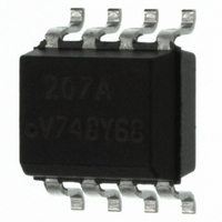
SFH6318T Vishay, SFH6318T Datasheet - Page 4

SFH6318T
Manufacturer Part Number
SFH6318T
Description
OPTOCOUPLER 100KBD 2600% 8SOIC
Manufacturer
Vishay
Datasheet
1.SFH6318T.pdf
(6 pages)
Specifications of SFH6318T
Isolation Voltage
4000 Vrms
Voltage - Isolation
4000Vrms
Number Of Channels
1, Unidirectional
Current - Output / Channel
60mA
Propagation Delay High - Low @ If
2µs @ 1.6mA
Current - Dc Forward (if)
20mA
Input Type
DC
Output Type
Logic
Mounting Type
Surface Mount
Package / Case
8-SOIC (3.9mm Width)
Current Transfer Ratio (max)
2600% @ 1.6mA
Current Transfer Ratio (min)
300% @ 1.6mA
Output Device
Photodarlington
Configuration
1 Channel
Current Transfer Ratio
2600 %
Maximum Baud Rate
100 KBps
Maximum Forward Diode Voltage
1.7 V
Maximum Reverse Diode Voltage
3 V
Maximum Input Diode Current
20 mA
Maximum Power Dissipation
150 mW
Maximum Operating Temperature
+ 100 C
Minimum Operating Temperature
- 55 C
No. Of Channels
1
Optocoupler Output Type
Photodarlington
Input Current
1.6mA
Output Voltage
7V
Opto Case Style
SOIC
No. Of Pins
8
Propagation Delay Low-high
35µs
Lead Free Status / RoHS Status
Lead free / RoHS Compliant
Voltage - Output
-
Vce Saturation (max)
-
Lead Free Status / RoHS Status
Lead free / RoHS Compliant, Lead free / RoHS Compliant
SFH6318T, SFH6319T
Vishay Semiconductors
Note
• Common mode transient immunity in logic high level is the maximum tolerable (positive) dV
Note
• As per IEC 60747-5-5, §7.4.3.8.1, this optocoupler is suitable for “safe electrical insulation” only within the safety ratings. Compliance with
www.vishay.com
4
COMMON MODE TRANSIENT IMMUNITY
PARAMETER
Common mode transient immunity
at logic high level output
Common mode transient immunity
at logic low level output
SAFETY AND INSULATION RATINGS
PARAMETER
Climatic Classification
(according to IEC 68 part 1)
Comparative Tracking Index
V
V
P
I
T
Creepage distance
Clearance distance
Insulation thickness
SI
pulse, V
maximum tolerable (negative) dV
logic low state (i.e.V
In applications where dv/dt may exceed 50,000 V/μs (such as state discharge) a series resistor, R
destructively high surge currents. The recommended value is refer to figure 2.
R
the safety ratings shall be ensured by means of protective circuits.
IOTM
IORM
SI
SO
CC
≅ [(IV)/0.15 I
CM
, to assure that the output will remain in a logic high state (i.e. V
isfh6318t_02
V
CC
B
F
(mA)] kΩ.
A
O
< 0.8 V).
I
F
cm
1
4
2
3
For technical questions, contact:
Fig. 2 - Test Circuit for Transient Immunity and Typical Waveforms
/dt
I
F
I
on
F
Pulse Generator
= 1.6 mA, R
TEST CONDITION
= 0 mA, R
the trailing edge of the common mode pulse signal, V
High Speed Optocoupler, 100 kBd,
+
V
CM
Low Input Current, High Gain
TEST CONDITION
–
L
L
= 2.2 kΩ, V
6
8
7
5
= 2.2 kΩ, V
R
CC
0.1 µF
(see Note 6)
CM
CM
220 Ω
= 10 V
= 10 V
optocoupleranswers@vishay.com
SYMBOL
CTI
P-P
R
O
P-P
L
> 2 V) common mode transient immunity in logic low level is the
+ 5 V
V
O
SYMBOL
|CM
|CM
V
V
O
O
H
H
MIN.
6000
175
560
Switch at A: I
0.2
|
|
V
Switch at B: I
4
4
CM
0 V
cm
10 %
/dt
MIN.
CM
on
, to assure that the output will remain in a
55/100/21
CC
F
F
the leading edge of the common mode
= 0 mA
TYP.
90 %
should be included to protect I
= 1.6 mA
t r
t
f
+ t
TYP.
f
=16 ns
1K
1K
90 %
Document Number: 83678
MAX.
399
350
150
165
10 %
MAX.
5 V
Rev. 1.8, 19-Oct-10
t
V
f
OL
UNIT
mW
mm
mm
mm
mA
UNIT
V/μs
V/μs
°C
V
V
C
from


