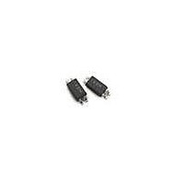
ACPL-214-500E Avago Technologies US Inc., ACPL-214-500E Datasheet - Page 7

ACPL-214-500E
Manufacturer Part Number
ACPL-214-500E
Description
ISOLATOR 3KVRMS 1CH TRANS SO-4
Manufacturer
Avago Technologies US Inc.
Datasheet
1.ACPL-214-500E.pdf
(7 pages)
Specifications of ACPL-214-500E
Output Type
Transistor
Input Type
AC, DC
Package / Case
SO-4
Mounting Type
Surface Mount
Voltage - Output
80V
Number Of Channels
1
Current - Output / Channel
50mA
Current - Dc Forward (if)
±50mA
Voltage - Isolation
3000Vrms
Vce Saturation (max)
400mV
Current Transfer Ratio (max)
400% @ ±1mA
Current Transfer Ratio (min)
20% @ ±1mA
Maximum Fall Time
3 us
Maximum Input Diode Current
1 mA
Maximum Rise Time
2 us
Output Device
Phototransistor
Configuration
1 Channel
Maximum Collector Emitter Voltage
80 V
Maximum Collector Emitter Saturation Voltage
0.4 V
Isolation Voltage
3000 Vrms
Current Transfer Ratio
20 %
Maximum Forward Diode Voltage
1.4 V
Maximum Collector Current
50 mA
Maximum Power Dissipation
200 mW
Maximum Operating Temperature
+ 110 C
Minimum Operating Temperature
- 55 C
Lead Free Status / RoHS Status
Lead free / RoHS Compliant
Lead Free Status / RoHS Status
Lead free / RoHS Compliant, Lead free / RoHS Compliant
Available stocks
Company
Part Number
Manufacturer
Quantity
Price
Company:
Part Number:
ACPL-214-500E
Manufacturer:
AVAGO
Quantity:
972
Part Number:
ACPL-214-500E
Manufacturer:
AVAGO/安华高
Quantity:
20 000
Figure 15. Collector Current vs. Ambient Temperature
Figure 17. Switching Time vs. Ambient Temperature
Figure 19. Frequency Response
For product information and a complete list of distributors, please go to our web site:
Avago, Avago Technologies, and the A logo are trademarks of Avago Technologies in the United States and other countries.
Data subject to change. Copyright © 2005-2011 Avago Technologies. All rights reserved.
AV02-0469EN - August 3, 2011
100
0.1
100
-2
-4
-6
-8
10
0.1
0
10
1
1
-25
1
-20
V
I
T a =
C
CC
I
V
R
= 2mA
F
CC
L
= 16mA
= 5V
= 1.9kΩ
= 5V
25°C
0
0
Ambient Temperature, Ta (°C)
Ambient Temperature, Ta (°C)
20
Frequency, f (kHz)
25
10
40
50
60
I
25mA
10mA
5mA
1mA
F
= 0.5mA
t
OFF
75
80
R
1kΩ
L
t
t
= 100Ω
ON
S
100
100
100
www.avagotech.com
Figure 16. Switching Time vs. Load Resistance
Figure 18. Collector-Emitter Saturation Voltage vs. Forward Current
Figure 20. CMR Test Circuit
1000
100
0.1
(High Voltage Pulse)
10
1
5
4
3
2
1
0
1
0
470 Ω
Ta = 25°C
V
R
V
R
CC
L
CM
L
= 1.9kΩ
= 5V
Vo
5
Load Resistance, R
Vcc
9V
Forward Current, I
t
OFF
V
current in floating capacitance between primary and
secondary sides.
V
Vo
cp
CM
: Voltage that is generated by the displacement
10
10
T
S
t
ON
L
V
V
F
cp
(kΩ)
(mA)
cp
≈ (dV/dt)xC
dV/dt
15
f
xR
L
Ta = 25°C
V
np
100
20


