8018630000 Weidmuller, 8018630000 Datasheet - Page 48
8018630000
Manufacturer Part Number
8018630000
Description
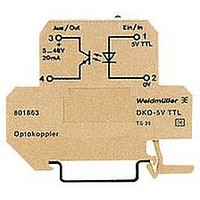
OPTOCOUPLER DISCRETE DK4O TS35
Manufacturer
Weidmuller
Specifications of 8018630000
Number Of Channels
1
Input Type
DC
Voltage - Output
5V
Current - Output / Channel
20mA
Output Type
Transistor
Mounting Type
DIN Rail
Package / Case
Module
No. Of Channels
1
Optocoupler Output Type
Transistor
Input Current
10mA
Output Voltage
48V
Opto Case Style
Module
No. Of Pins
4
Peak Reflow Compatible (260 C)
No
Input Current Max
10mA
Output Voltage Max
48V
Rohs Compliant
Yes
Leaded Process Compatible
No
Lead Free Status / RoHS Status
Lead free / RoHS Compliant
Current - Dc Forward (if)
-
Voltage - Isolation
-
Vce Saturation (max)
-
Current Transfer Ratio (max)
-
Current Transfer Ratio (min)
-
Other names
DKO OPTO COUPLER TS


With increasing automation, potential
separation between the control and field
sides of circuits is becoming increasingly
important. The control unit being the core
of the automation must be electrically safe
and free from feedback when coupled with
the various sensors and actuators. Opto-
coupler are being used in a growing num-
ber of applications. They offer the neces-
sary safety and have further advantages
such as:
- low power uptake on control side
- high switching frequency
- no contact bounce
- wear-free switching
- insensitive to vibration
- use independent of location
- no mechanical parts
- long life
- high insulation voltage
Because of these features, opto-coupler
are an alternative to conventional, me-
chanical relay interfaces.
For industrial usage, Weidmüller offers
modules with various input voltages and
housings.
Opto-coupler
Basic construction of the opto-coupler
interface:
The heart of the system is the opto-
electronic component (opto-coupler) that
effects the coupling.
Input from
control
An important parameter of this type of
modules is the CTR = current transfer
rate.
The CTR is given in % and is the ratio
between the input current IF and the
maximum available output current IC.
Example: IF = 10 mA; CTR = 100%
The CTR is affected by a number of
parameters such as:
- Ambient temperature
- efficiency of the luminescence diode
- geometric dimensions within the module
It also drops with time. The result is that
the switching levels change due to ageing.
CTR as a function of operating life
CTR
in %
Sender
=> IC = 10 mA.
Receiver
Output to
periphery
t (Life time)
To eliminate these effects where possible,
Weidmüller opto-coupler use almost
exclusively semiconductors which have a
long life in terms of CTR.
Moreover, the insulation of a module is
highly important, since the actual coupling
of the input and output circuits takes
place optically. Thus the optical
component has to guarantee separation of
both circuits even in case of a defect.
Weidmüller opto-coupler comply with
DIN VDE 0884 to provide a maximum level
of safety.
Appropriate switching circuits need to be
included to ensure that the entire com-
ponent provides reliable separation in
accordance with DIN VDE 0106,
Part 101.
Circuit diagram of an opto-coupler
Opto-coupler for protective separation
or galvanic isolation
The most important precondition for
achieving protective separation with opto-
electronic coupling modules is the partial
discharge test in accordance with DIN
VDE 0884. Double or reinforced insulation
for protective separation must be dis-
charge proof. High voltage tests, as are
usual with relays, cannot be carried out
with semi-conductors, because they could
lead to the destruction of the semi-con-
ductor. Safe separation for the given rated
voltage is applicable to coupling modules
that are integrated into opto-couplers if:
- the opto-couplers are tested according
- clearance and creepage distances on
to DIN VDE 0884
the PCB and connection elements cor-
respond to EN 50 178, DIN VDE 0106
and 0109.
105
Related parts for 8018630000
Image
Part Number
Description
Manufacturer
Datasheet
Request
R


Part Number:
Description:
PLUG BANA STD .080" PIN SET/2
Manufacturer:
E-Z-Hook
Datasheet:

Part Number:
Description:
RF Connectors SMA Plug Termination Straight Male
Manufacturer:
Amphenol

Part Number:
Description:
RF Connectors SMA Plug Termination with Beaded Chain
Manufacturer:
Amphenol


Part Number:
Description:
Conn Socket Strip SKT 36 POS 2.54mm Solder ST Thru-Hole
Manufacturer:
Precidip
Part Number:
Description:
Conn Socket Strip SKT 10 POS 2.54mm Solder ST Thru-Hole
Manufacturer:
Precidip
Part Number:
Description:
Conn Socket Strip SKT 50 POS 2.54mm Solder ST Thru-Hole
Manufacturer:
Precidip
Part Number:
Description:
Conn Socket Strip RCP 5 POS 2.54mm Solder ST Thru-Hole Box
Manufacturer:
Precidip
Part Number:
Description:
Conn Socket Strip RCP 7 POS 2.54mm Solder ST Thru-Hole Box
Manufacturer:
Precidip