8018630000 Weidmuller, 8018630000 Datasheet - Page 64
8018630000
Manufacturer Part Number
8018630000
Description
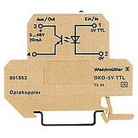
OPTOCOUPLER DISCRETE DK4O TS35
Manufacturer
Weidmuller
Specifications of 8018630000
Number Of Channels
1
Input Type
DC
Voltage - Output
5V
Current - Output / Channel
20mA
Output Type
Transistor
Mounting Type
DIN Rail
Package / Case
Module
No. Of Channels
1
Optocoupler Output Type
Transistor
Input Current
10mA
Output Voltage
48V
Opto Case Style
Module
No. Of Pins
4
Peak Reflow Compatible (260 C)
No
Input Current Max
10mA
Output Voltage Max
48V
Rohs Compliant
Yes
Leaded Process Compatible
No
Lead Free Status / RoHS Status
Lead free / RoHS Compliant
Current - Dc Forward (if)
-
Voltage - Isolation
-
Vce Saturation (max)
-
Current Transfer Ratio (max)
-
Current Transfer Ratio (min)
-
Other names
DKO OPTO COUPLER TS


Opto-couplers DKO
S0 signal sensor
Application example:
Signals for consumers are normally transferred
via an interface. Generally, this interface must
conform with DIN 43867 (interface for signal
transmission). There must be a differentiation
between the passive interface and active S0
interface. The actual signals, that are corres-
pondingly proportional to the relevant con-
sumption (electrical energy, gas consumption,
water, district heating, etc.) are shown at
measuring sensors (electric meter, etc.) The
interface itself is purely passive (acceptor) and
must be supplied via a source. The source for
providing the current is built into the active
interface. The following threshold values are
specified:
For the recognition of the corresponding con-
sumption signals, the following currents are
integrated:
The module accepts the input from the signal
sensor and outputs the opto-decoupled output
signal, i. e. galvanically isolated.
For TS 32
For TS 35
With combination foot TS 32 / TS 35
Input
Input voltage
Input current
Pulse generator
Output
Output voltage
Output current
Voltage proof input-output/mounting rail
Rated voltage
Rated impulse voltage
Overvoltage category
Pollution severity
Clearances and creepage distances
Operating temperature
Storage temperature
Conductor
Conductor cross-section
Overall width
End plate
Ordering data
Technical data
Insulation coordination to DIN VDE 0160, Draft 11/94
Accessories
Opto-coupler in component housing mini coupler DK
I
U
f
ON (active) -> 10…27 mA
Off (inactive) -> 0…2 mA
max
max
max
= 27 mAdc
= 16.66 Hz
= 27 Vdc
without clearances
with clearances
W
Y
DKO switching amplifiers/opto-couplers for Namur initiators
DKO DK4 S0
DKO DK4 S0
DKO DK4 S0
24 Vdc ±10 %
≤13 mA
Specification acc. to DIN
43864 (current interface for
connection to pulse generator
acc. to DIN 43864)
5…48 Vdc
max. 100 mA
4 kV
300 V
6 kV
IV
2
≥5.5 mm
-25 °C…+40 °C
-25 °C…+50 °C
-40 °C…+60 °C
AWG 22…12
0.5…4 mm
12 mm
AP DKT4
Schematic circuit diagram
Type
Type
eff
2
Cat. No.
8467030000
8100180000
Cat. No.
0687560000
For TS 32
For TS 35
With combination foot TS 32 / TS 35
Input
Input voltage
Input current
Reverse polarity protection
NAMUR-Input (N+ and N-)
Switching frequency
Switch-on delay
Switch-off delay
Input (E+ and 0)
Switch-on point
Switch off-point
Current consumption
Max. switching frequency
Switch-on delay
Switch-off delay
Output (A+ and A-)
Output voltage
Output current
Switching capacity
Internal voltage drop
Protective measure
Voltage proof input-output/mounting rail
Operating temperature
Storage temperature
Conductor
Conductor cross-section
Overall width
End plate
Ordering data
Technical data
Accessories
W
without clearances
with clearances
W
Y
DKO
24 Vdc ±20 %
≤35 mA
up to 1 kV available
300 Hz f. pulse duty factor 1:1
approx.45 µs
approx.450 µs
approx.18 V
ca 15 V
< 5 mA
300 Hz f. pulse duty factor 1:1
approx.20µs
approx.400 µs
5…30 Vdc
max. 100 mA
max. 3 W
max. 1 V
Free-wheel. diode btwn. A+…A-
4 kV
-25 °C…+40 °C
-25 °C…+50 °C
-40 °C…+60 °C
AWG 22…12
0.5…4 mm
12 mm
AP DKT4
DKO
Schematic circuit diagram
Type
Type
eff
2
Cat. No.
8164250000
Cat. No.
0687560000
121
Related parts for 8018630000
Image
Part Number
Description
Manufacturer
Datasheet
Request
R


Part Number:
Description:
PLUG BANA STD .080" PIN SET/2
Manufacturer:
E-Z-Hook
Datasheet:

Part Number:
Description:
RF Connectors SMA Plug Termination Straight Male
Manufacturer:
Amphenol

Part Number:
Description:
RF Connectors SMA Plug Termination with Beaded Chain
Manufacturer:
Amphenol


Part Number:
Description:
Conn Socket Strip SKT 36 POS 2.54mm Solder ST Thru-Hole
Manufacturer:
Precidip
Part Number:
Description:
Conn Socket Strip SKT 10 POS 2.54mm Solder ST Thru-Hole
Manufacturer:
Precidip
Part Number:
Description:
Conn Socket Strip SKT 50 POS 2.54mm Solder ST Thru-Hole
Manufacturer:
Precidip
Part Number:
Description:
Conn Socket Strip RCP 5 POS 2.54mm Solder ST Thru-Hole Box
Manufacturer:
Precidip
Part Number:
Description:
Conn Socket Strip RCP 7 POS 2.54mm Solder ST Thru-Hole Box
Manufacturer:
Precidip