W7CF128M1XA-H20PC-001.01 Wintec Industries, W7CF128M1XA-H20PC-001.01 Datasheet - Page 23
W7CF128M1XA-H20PC-001.01
Manufacturer Part Number
W7CF128M1XA-H20PC-001.01
Description
IC MEMORY
Manufacturer
Wintec Industries
Datasheet
1.W7CF128M1XA-H20PC-001.01.pdf
(50 pages)
Specifications of W7CF128M1XA-H20PC-001.01
Memory Size
128M bytes
Memory Type
CompactFLASH
Lead Free Status / RoHS Status
Lead free / RoHS Compliant
Other names
385-1037


WintecCF-W7CF-H_v2.2 ROHS
June 2006 Wintec Industries, Inc.
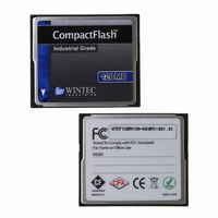
INDUSTRIAL GRADE CompactFlash
W7CFxxxA-H Series ROHS 6/6 Compliant
32MB – 8-GB
2.4.7 Cylinder High Register
This register contains the high 8-bit of the starting cylinder address, which is started by following sector transfer command.
2.4.8 Drive Head Register
This register is used for selecting the Drive number and head number for the following command.
NOTE:
2.4.9 Status Register
This register is read only register, and it indicates the card status of command execution. When this register is read in configured
I/O card mode (INDEX = 1, 2, 3) and level interrupt mode, -IREQ is negated. This register should be accessed in byte mode. In
word mode, it is recommended that Alternate status register may be used as this register.
3 -0
bit
bit
1. DRV: Drive number
bit 7
bit 7
7
6
5
4
bit 7
BSY
7
6
5
4
3
2
1
0
1
BSY (BuSY)
DRDY (Drive ReaDY)
DWF (Drive Write Full)
DSC (Drive Seek Complete)
DRQ (Data ReQuest)
CORR (CORRected data)
IDX (InDeX)
ERR (ERRor)
DRV (DRiVe select)
Head number
DRDY
LBA
bit 6
bit 6
bit 6
Name
LBA
1
1
Name
DWF
bit 5
bit 5
bit 5
1
This bit is set to “1”.
LBA is a flag to select either Cylinder / Head / Sector (CHS) or Logical Block
Address (LBA) mode. When LBA = 0, CHS mode is selected. When LBA = 1, LBA
mode is selected. In LBA mode, the Logical Block Address is interrupted as follows:
LBA07 - LBA00: Sector Number Register D7 - D0.
LBA15 - LBA08: Cylinder Low Register D7 - D0.
LBA23 - LBA16: Cylinder High Register D7 - D0.
LBA27 - LBA24: Drive / Head Register bits HS3 - HS0.
This bit is set to “1”.
This bit is used for selecting the Master (Card 0) and Slave (Card 1) in Master/Slave
organization. The card is set to be Card 0 or 1 by using DRV# of the Socket and Copy
register.
This bit is used for selecting the Head number for the following command. Bit 3 is
MSB.
TM
This bit is set when the card internal operation is executing. When this bit is set
to “1”, other bits in this register are invalid.
If this bit and DSC bit are set to “1”, the card is capable of receiving the read
or write or seek requests. If this bit is set to “0”, the card prohibits these
requests.
This bit is set if this card indicates the write fault status.
This bit is set when the drive seek complete.
This bit is set when the information can be transferred between the host and
Data register. This bit is cleared when the card receives the other command.
This bit is set when a correctable data error has been occurred and the data has
been corrected.
This bit is always set to “0”.
This bit is set when the previous command has ended in some type of error.
The error information is set in the other Status register or Error register. This
bit is cleared by the next command.
Disk
DRV
bit 4
bit 4
bit 4
DSC
Cylinder high byte
Head #
DRQ
bit 3
bit 3
bit 3
Function
Function
CORR
bit 2
bit 2
bit 2
bit 1
bit 1
bit 1
IDX
ERR
bit 0
bit 0
bit 0
21
Related parts for W7CF128M1XA-H20PC-001.01
Image
Part Number
Description
Manufacturer
Datasheet
Request
R

Part Number:
Description:
MEMORY CARD COMPACTFLASH 128MB
Manufacturer:
Wintec Industries

Part Number:
Description:
HDD ENCLOSURE 3.5 USB 2.0 WHT
Manufacturer:
Wintec Industries
Datasheet:

Part Number:
Description:
HDD ENCLOSURE 2.5 USB 2.0 BK
Manufacturer:
Wintec Industries
Datasheet:

Part Number:
Description:
HDD ENCLOSURE 2.5 USB 2.0 WHT
Manufacturer:
Wintec Industries
Datasheet:

Part Number:
Description:
HDD ENCLOSURE 3.5 USB 2.0 BK
Manufacturer:
Wintec Industries
Datasheet:

Part Number:
Description:
EMBEDDED MODEM W/FUSE 33.6KBPS
Manufacturer:
Wintec Industries
Datasheet:

Part Number:
Description:
EMBEDDED MODEM W/FUSE 33.6KBPS
Manufacturer:
Wintec Industries
Datasheet:

Part Number:
Description:
EMBEDDED MODEM W/FUSE 56KBPS
Manufacturer:
Wintec Industries
Datasheet:

Part Number:
Description:
COMPACT FLASH INDUSTRIAL 1GB
Manufacturer:
Wintec Industries

Part Number:
Description:
COMPACT FLASH INDSTRL 512MB
Manufacturer:
Wintec Industries

Part Number:
Description:
COMPACT FLASH INDUSTRIAL 4GB
Manufacturer:
Wintec Industries

Part Number:
Description:
COMPACT FLASH INDUSTRIAL 1GB
Manufacturer:
Wintec Industries

Part Number:
Description:
COMPACT FLASH INDUSTRIAL 2GB
Manufacturer:
Wintec Industries

Part Number:
Description:
COMPACT FLASH INDUSTRIAL 2GB
Manufacturer:
Wintec Industries
Datasheet:

Part Number:
Description:
COMPACT FLASH INDUSTRIAL 4GB
Manufacturer:
Wintec Industries