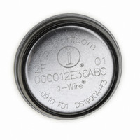
DS1922E-F5# Maxim Integrated Products, DS1922E-F5# Datasheet - Page 14

DS1922E-F5#
Manufacturer Part Number
DS1922E-F5#
Description
IBUTTON TEMP LOGGER 4KBit F5
Manufacturer
Maxim Integrated Products
Series
iButton®r
Datasheet
1.DS1922E-F5.pdf
(44 pages)
Specifications of DS1922E-F5#
Rohs Information
IButton RoHS Compliance Plan
Memory Size
512B
Memory Type
NVSRAM (Non-Volatile SRAM)
Lead Free Status / RoHS Status
Lead free by exemption / RoHS compliant by exemption
High-Temperature Logger iButton with 8KB
Data-Log Memory
The DS1922E has two Temperature Alarm Threshold
registers (address 0208h, 0209h) to store values that
determine whether a critical temperature has been
reached. A temperature alarm is generated if the
device measures an alarming temperature and the
alarm signaling is enabled. The bits ETLA and ETHA
that enable the temperature alarm are located in the
Temperature Sensor Control register. The temperature
alarm flags TLF and THF are found in the Alarm Status
register at address 0214h.
Bit 1: Enable Temperature High Alarm (ETHA). This
bit controls whether, during a mission, the temperature
high alarm flag (THF) may be set, if a temperature con-
version results in a value equal to or higher than the
value in the Temperature High Alarm Threshold register.
If ETHA is 1, temperature high alarms are enabled. If
ETHA is 0, temperature high alarms are not generated.
Bit 0: Enable Temperature Low Alarm (ETLA). This
bit controls whether, during a mission, the temperature
low alarm flag (TLF) may be set, if a temperature con-
version results in a value equal to or lower than the
value in the Temperature Low Alarm Threshold register.
If ETLA is 1, temperature low alarms are enabled. If
ETLA is 0, temperature low alarms are not generated.
Note: During a mission, there is only read access to this register. Bits 2 to 7 have no function. They always read 0 and cannot be
written to 1.
Note: During a mission, there is only read access to this register. Bits 2 to 7 have no function. They always read 0 and cannot be
written to 1.
14
ADDRESS
ADDRESS
0212h
0210h
______________________________________________________________________________________
BIT 7
BIT 7
0
0
Temperature Sensor Alarm
BIT 6
BIT 6
0
0
BIT 5
BIT 5
0
0
BIT 4
BIT 4
0
0
To minimize the power consumption of a DS1922E, the
RTC oscillator should be turned off when the device is
not in use. The oscillator on/off bit is located in the RTC
Control register. This register also includes the EHSS
bit, which determines whether the sample rate is speci-
fied in seconds or minutes.
Bit 1: Enable High-Speed Sample (EHSS). This bit
controls the speed of the sample rate counter. When set
to logic 0, the sample rate is specified in minutes. When
set to logic 1, the sample rate is specified in seconds.
Bit 0: Enable Oscillator (EOSC). This bit controls the
crystal oscillator of the RTC. When set to logic 1, the
oscillator starts. When written to logic 0, the oscillator
stops and the device is in a low-power data-retention
mode. This bit must be 1 for normal operation. A Forced
Conversion or Start Mission command automatically
starts the RTC by changing the EOSC bit to logic 1.
Temperature Sensor Control Register
BIT 3
BIT 3
0
0
BIT 2
BIT 2
0
0
RTC Control Register
EHSS
BIT 1
ETHA
BIT 1
RTC Control
EOSC
BIT 0
ETLA
BIT 0


