DS1922E-F5# Maxim Integrated Products, DS1922E-F5# Datasheet - Page 23
DS1922E-F5#
Manufacturer Part Number
DS1922E-F5#
Description
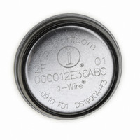
IBUTTON TEMP LOGGER 4KBit F5
Manufacturer
Maxim Integrated Products
Series
iButton®r
Datasheet
1.DS1922E-F5.pdf
(44 pages)
Specifications of DS1922E-F5#
Rohs Information
IButton RoHS Compliance Plan
Memory Size
512B
Memory Type
NVSRAM (Non-Volatile SRAM)
Lead Free Status / RoHS Status
Lead free by exemption / RoHS compliant by exemption


This command is used to verify scratchpad data and
target address. After issuing the Read Scratchpad
command, the master begins reading. The first 2 bytes
are the target address. The next byte is the ending off-
set/data status byte (E/S) followed by the scratchpad
data beginning at the byte offset T[4:0], as shown in
Figure 8. The master can continue reading data until
the end of the scratchpad after which it receives an
inverted CRC-16 of the command code, target
addresses TA1 and TA2, the E/S byte, and the scratch-
pad data starting at the target address. After the CRC
is read, the bus master reads logic 1s from the
DS1922E until a reset pulse is issued.
This command is used to copy data from the scratch-
pad to the writable memory sections. After issuing the
Copy Scratchpad command, the master must provide a
3-byte authorization pattern, which can be obtained by
reading the scratchpad for verification. This pattern
must exactly match the data contained in the three
address registers (TA1, TA2, E/S, in that order). Next,
the master must transmit the 64-bit full-access pass-
word. If passwords are enabled and the transmitted
password is different from the stored full-access pass-
word, the Copy Scratchpad with Password command
fails. The device stops communicating and waits for a
reset pulse. If the password was correct or if pass-
words were not enabled, the device tests the 3-byte
authorization code. If the authorization code pattern
matches, the AA flag is set and the copy begins. A pat-
tern of alternating 1s and 0s is transmitted after the
data has been copied until the master issues a reset
pulse. While the copy is in progress, any attempt to
reset the part is ignored. Copy typically takes 2µs per
byte.
The data to be copied is determined by the three
address registers. The scratchpad data from the begin-
ning offset through the ending offset are copied, start-
ing at the target address. The AA flag remains at logic
1 until it is cleared by the next Write Scratchpad com-
mand. With suitable password, the copy scratchpad
always functions for the 16 pages of data memory and
the 2 pages of calibration memory. While a mission is in
Copy Scratchpad with Password [99h]
High-Temperature Logger iButton with 8KB
Read Scratchpad Command [AAh]
______________________________________________________________________________________
progress, write attempts to the register pages are not
successful. The AA bit remaining at 0 indicates this.
The Read Memory with CRC command is the general
function to read from the device. This command gener-
ates and transmits a 16-bit CRC following the last data
byte of a memory page.
After having sent the command code of the Read
Memory with CRC command, the bus master sends a
2-byte address that indicates a starting byte location.
Next, the master must transmit one of the 64-bit pass-
words. If passwords are enabled and the transmitted
password does not match one of the stored passwords,
the Read Memory with Password and CRC command
fails. The device stops communicating and waits for a
reset pulse. If the password was correct or if pass-
words were not enabled, the master reads data from
the DS1922E beginning from the starting address and
continuing until the end of a 32-byte page is reached.
At that point the bus master sends 16 additional read
data time slots and receives the inverted 16-bit CRC.
With subsequent read data time slots the master
receives data starting at the beginning of the next
memory page followed again by the CRC for that page.
This sequence continues until the bus master resets the
device. When trying to read the passwords or memory
areas that are marked as “reserved,” the DS1922E
transmits 00h or FFh bytes, respectively. The CRC at
the end of a 32-byte memory page is based on the
data as it was transmitted.
With the initial pass through the Read Memory with
CRC flow, the 16-bit CRC value is the result of shifting
the command byte into the cleared CRC generator fol-
lowed by the two address bytes and the contents of the
data memory. Subsequent passes through the Read
Memory with CRC flow generate a 16-bit CRC that is
the result of clearing the CRC generator and then shift-
ing in the contents of the data memory page. After the
16-bit CRC of the last page is read, the bus master
receives logic 1s from the DS1922E until a reset pulse
is issued. The Read Memory with CRC command
sequence can be ended at any point by issuing a reset
pulse.
Read Memory with Password and CRC
Data-Log Memory
[69h]
23
Related parts for DS1922E-F5#
Image
Part Number
Description
Manufacturer
Datasheet
Request
R

Part Number:
Description:
High-Temperature Logger iButton with 8KB Data-Log Memory
Manufacturer:
MAXIM [Maxim Integrated Products]
Datasheet:
Part Number:
Description:
High-Temperature Logger iButton with 8KB
Manufacturer:
MAXIM [Maxim Integrated Products]
Datasheet:

Part Number:
Description:
MAX7528KCWPMaxim Integrated Products [CMOS Dual 8-Bit Buffered Multiplying DACs]
Manufacturer:
Maxim Integrated Products
Datasheet:
Part Number:
Description:
Single +5V, fully integrated, 1.25Gbps laser diode driver.
Manufacturer:
Maxim Integrated Products
Datasheet:
Part Number:
Description:
Single +5V, fully integrated, 155Mbps laser diode driver.
Manufacturer:
Maxim Integrated Products
Datasheet:
Part Number:
Description:
VRD11/VRD10, K8 Rev F 2/3/4-Phase PWM Controllers with Integrated Dual MOSFET Drivers
Manufacturer:
Maxim Integrated Products
Datasheet:
Part Number:
Description:
Highly Integrated Level 2 SMBus Battery Chargers
Manufacturer:
Maxim Integrated Products
Datasheet:
Part Number:
Description:
Current Monitor and Accumulator with Integrated Sense Resistor; ; Temperature Range: -40°C to +85°C
Manufacturer:
Maxim Integrated Products
Part Number:
Description:
TSSOP 14/A°/RS-485 Transceivers with Integrated 100O/120O Termination Resis
Manufacturer:
Maxim Integrated Products
Part Number:
Description:
TSSOP 14/A°/RS-485 Transceivers with Integrated 100O/120O Termination Resis
Manufacturer:
Maxim Integrated Products
Part Number:
Description:
QFN 16/A°/AC-DC and DC-DC Peak-Current-Mode Converters with Integrated Step
Manufacturer:
Maxim Integrated Products
Part Number:
Description:
TDFN/A/65V, 1A, 600KHZ, SYNCHRONOUS STEP-DOWN REGULATOR WITH INTEGRATED SWI
Manufacturer:
Maxim Integrated Products
Part Number:
Description:
Integrated Temperature Controller f
Manufacturer:
Maxim Integrated Products
Part Number:
Description:
SOT23-6/I°/45MHz to 650MHz, Integrated IF VCOs with Differential Output
Manufacturer:
Maxim Integrated Products
Part Number:
Description:
SOT23-6/I°/45MHz to 650MHz, Integrated IF VCOs with Differential Output
Manufacturer:
Maxim Integrated Products