MT18VDDF12872HG-40BD1 Micron Technology Inc, MT18VDDF12872HG-40BD1 Datasheet - Page 16
MT18VDDF12872HG-40BD1
Manufacturer Part Number
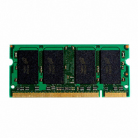
MT18VDDF12872HG-40BD1
Description
MODULE DDR SDRAM 1GB 200-SODIMM
Manufacturer
Micron Technology Inc
Datasheet
1.MT18VDDF12872HY-40BF1.pdf
(26 pages)
Specifications of MT18VDDF12872HG-40BD1
Memory Type
DDR SDRAM
Memory Size
1GB
Speed
200MHz
Package / Case
200-SODIMM
Lead Free Status / RoHS Status
Contains lead / RoHS non-compliant
Other names
557-1116


Notes
pdf: 09005aef80e4880c, source: 09005aef80e487d7
DDAF18C128x72HG.fm - Rev. A 10/04 EN
10. I
11. This parameter is sampled. V
1. All voltages referenced to V
2. Tests for AC timing, I
3. Outputs measured with equivalent load:
4. AC timing and I
5. The AC and DC input level specifications are as
6. V
7. V
8. I
9. Enables on-chip refresh and address counters.
characteristics may be conducted at nominal ref-
erence/supply voltage levels, but the related spec-
ifications and device operation are guaranteed for
the full voltage range specified.
swing of up to 1.5V in the test environment, but
input timing is still referenced to V
crossing point for CK/CK#), and parameter speci-
fications are guaranteed for the specified AC input
levels under normal use conditions. The mini-
mum slew rate for the input signals used to test
the device is 1V/ns in the range between V
and V
defined in the SSTL_2 Standard (i.e., the receiver
will effectively switch as a result of the signal
crossing the AC input level, and will remain in that
state as long as the signal does not ring back
above [below] the DC input LOW [HIGH] level).
ting device and to track variations in the DC level
of the same. Peak-to-peak noise (non-common
mode) on V
DC value. Thus, from V
±25mV for DC error and an additional ±25mV for
AC noise. This measurement is to be taken at the
nearest V
system supply for signal termination resistors, is
expected to be set equal to V
variations in the DC level of V
rates. Specified values are obtained with mini-
mum cycle time at CL = 3 with the outputs open.
properly initialized, and is averaged at the defined
cycle rate.
V
25°C, V
DD
DD
REF
TT
DD
Q = +2.5V ±0.2V, V
is not applied directly to the device. V
is dependent on output loading and cycle
specifications are tested after the device is
is expected to equal V
IH
OUT
(AC).
REF
(DC) = V
REF
Output
(V
bypass capacitor.
OUT
may not exceed ±2 percent of the
)
DD
DD
DD
V
tests may use a V
TT
REF
Q/2, V
50
30pF
, and electrical AC and DC
Reference
Point
DD
= V
SS
DD
Q/2, V
.
OUT
SS
REF
Q/2 of the transmit-
REF
DD
, f = 100 MHz, T
.
(peak to peak) =
and must track
= +2.5V ±0.2V,
REF
REF
is allowed
(or to the
IL
-to-V
TT
IL
(AC)
is a
A
IH
=
16
12. For slew rates < 1 V/ns and to 0.5 Vns. If the slew
13. The CK/CK# input reference level (for timing ref-
14. Inputs are not recognized as valid until V
15. The output timing reference level, as measured at
16.
17. The intent of the Don’t Care state after completion
18. This is not a device limit. The device will operate
19. It is recommended that DQS be valid (HIGH or
20. MIN (
21. The refresh period 64ms. This equates to an aver-
0.2V. DM input is grouped with I/O pins, reflecting
the fact that they are matched in loading.
rate is < 0.5V/ns, timing must be derated:
an additional 50ps per each 100 mV/ns reduction
in slew rate from 500mV/ns, while
fected. If the slew rate exceeds 4.5 V/ns, function-
ality is uncertain. For -40B, slew rates must be
0.5 V/ns.
erenced to CK/CK#) is the point at which CK and
CK# cross; the input reference level for signals
other than CK/CK# is V
lizes. Exception: during the period before V
stabilizes, CKE 0.3 x V
the timing reference point indicated in Note 3, is
V
t
time windows as valid data transitions. These
parameters are not referenced to a specific voltage
level, but specify when the device output is no
longer driving (HZ) or begins driving (LZ).
of the postamble is the DQS-driven signal should
either be high, low, or high-Z and that any signal
transition within the input switching region must
follow valid input requirements. That is, if DQS
transitions high (above V
not transition low (below V
(MIN).
with a negative value, but system performance
could be degraded due to bus turnaround.
LOW) on or before the WRITE command. The
case shown (DQS going from High-Z to logic
LOW) applies when no WRITEs were previously in
progress on the bus. If a previous WRITE was in
progress, DQS could be HIGH during this time,
depending on
smallest multiple of
absolute Value for the respective parameter.
(MAX) for I
ple of
value for
age refresh rate of 7.8125µs. However, an AUTO
REFRESH command must be asserted at least
once every 70.3µs; burst refreshing or posting by
HZ and
Micron Technology, Inc., reserves the right to change products or specifications without notice.
TT
.
1GB (x72, ECC, DR) PC3200
t
RC or
t
CK that meets the maximum absolute
t
t
LZ transitions occur in the same access
RAS.
DD
200-PIN DDR SODIMM
t
RFC) for I
t
measurements is the largest multi-
DQSS.
t
CK that meets the minimum
REF
DD
DD
IH
Q is recognized as LOW.
.
DC (MIN) then it must
IH
measurements is the
DC) prior to
©2004 Micron Technology, Inc.
t
IH is unaf-
REF
t
t
DQSH
IS has
stabi-
t
RAS
REF
Related parts for MT18VDDF12872HG-40BD1
Image
Part Number
Description
Manufacturer
Datasheet
Request
R

Part Number:
Description:
IC SDRAM 64MBIT 133MHZ 54TSOP
Manufacturer:
Micron Technology Inc
Datasheet:

Part Number:
Description:
IC SDRAM 64MBIT 5.5NS 86TSOP
Manufacturer:
Micron Technology Inc
Datasheet:
Part Number:
Description:
IC SDRAM 64MBIT 200MHZ 86TSOP
Manufacturer:
Micron Technology Inc
Datasheet:
Part Number:
Description:
IC SDRAM 64MBIT 133MHZ 54TSOP
Manufacturer:
Micron Technology Inc
Datasheet:
Part Number:
Description:
IC SDRAM 128MBIT 133MHZ 54TSOP
Manufacturer:
Micron Technology Inc
Datasheet:

Part Number:
Description:
IC SDRAM 256MBIT 133MHZ 90VFBGA
Manufacturer:
Micron Technology Inc
Datasheet:
Part Number:
Description:
IC SDRAM 128MBIT 133MHZ 54TSOP
Manufacturer:
Micron Technology Inc
Datasheet:
Part Number:
Description:
IC SDRAM 256MBIT 133MHZ 54TSOP
Manufacturer:
Micron Technology Inc
Datasheet:

Part Number:
Description:
IC DDR SDRAM 512MBIT 6NS 66TSOP
Manufacturer:
Micron Technology Inc
Datasheet:
Part Number:
Description:
IC SDRAM 128MBIT 167MHZ 86TSOP
Manufacturer:
Micron Technology Inc
Datasheet:
Part Number:
Description:
IC SDRAM 128MBIT 143MHZ 86TSOP
Manufacturer:
Micron Technology Inc
Datasheet:

Part Number:
Description:
SDRAM 256M-BIT 1.8V 54-PIN VFBGA
Manufacturer:
Micron Technology Inc
Datasheet:
Part Number:
Description:
IC SDRAM 128MBIT 143MHZ 86TSOP
Manufacturer:
Micron Technology Inc
Datasheet:

Part Number:
Description:
IC SDRAM 128MBIT 125MHZ 54VFBGA
Manufacturer:
Micron Technology Inc
Datasheet:
Part Number:
Description:
IC SDRAM 128MBIT 125MHZ 54VFBGA
Manufacturer:
Micron Technology Inc
Datasheet: