LQ038Q5DR01 Sharp Microelectronics, LQ038Q5DR01 Datasheet - Page 7
LQ038Q5DR01
Manufacturer Part Number
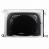
LQ038Q5DR01
Description
LCD TFT 3.8" 320X240 QVGA
Manufacturer
Sharp Microelectronics
Datasheet
1.LQ038Q5DR01.pdf
(26 pages)
Specifications of LQ038Q5DR01
Display Type
LCD - Color
Display Mode
*
Viewing Area
78.72mm L x 53.64mm W
Dot Pixels
320 x 240 (QVGA)
Pixel Density
320 x 240
Module Size (w X H X T)
117.5 mm x 69.45 mm x 13.45 mm
Viewing Area (w X H)
78.72 mm x 53.64 mm
Backlighting
White
Lead Free Status / RoHS Status
Contains lead / RoHS non-compliant
Interface
-
Backlight
-
Dot Size
-
Dot Pitch
-
Lead Free Status / Rohs Status
Details
Other names
425-2484
Available stocks
Company
Part Number
Manufacturer
Quantity
Price
Company:

Part Number:
LQ038Q5DR01
Manufacturer:
SHARP
Quantity:
1 000


【Note 4-1】
【Note 4-2】
ENAB is fixed “Low”, the horizontal start timing is determined as described in Fig3-A.
【Note 4-3】
【Note 4-4】
4-2)Back-light fluorescent tube driving part
No.
(5)Absolute maximum ratings
+3.3V power supply
Storage temperature
Operating temperature
(panel surface)
Operating temperature
( Ambient temperature )
【Note 5-1】 CK,R0∼R5,G0∼G5,B0∼B5,Hsync,Vsync,ENAB,HVR
【Note 5-2】 Humidity:95%RH Max. at Ta≦60℃
HVR = "Low" : Regular video
The position of pin number
The horizontal display start timing is settled in accordance with a rising timing of ENAB signal. In case
HVR = "High" : Horizontally and Vertically inverted video
(Don’t keep ENAB “High” during operation.(Fig3-B).)
Table 4-2
Table 5-1
1
2
Hsync
Vsync
Input voltage
Symbol
VL1
VL2
Parameter
Maximum wet-bulb temperature is less than at 58℃ at Ta>60℃.
Condensation of dew must be avoided as electrical current leaks will occur, causing a
Degradation of performance specifications.
4
0
3
9
Used connector:BHR-02(8.0)VS-1N(JST Co. ,Ltd)
Fit connctor:SM02(8.0)B-BHS-1N(JST Co. ,Ltd)
Used thermistor :203GT−1(Ishizuka electoronics Corporation)=20.0kΩ±3%
3
8
3
7
positive
positive
i/o
3
6
3
5
I
I
3
4
3
3
Function
input terminal (High Voltage)
input terminal (Low Voltage)
3
2
3
1
3
0
2
9
Symbol
Topr1
Topr2
Tstg
VCC
2
8
2
7
V
I
2
6
2
5
2
4
2
3
MIN
2
2
2
1
-0.3
-40
-30
-30
0
2
0
1
9
1
8
1
7
1
6
1
5
VCC+0.3
MAX
+95
+85
+60
1
4
1
3
5.5
Color of FL cable
RED
BLACK
1
2
1
1
1
0
9
Unit
V
℃
℃
℃
8
7
V
6
5
【Note 5-2】
【Note 5-2】
【Note 5-2】
【Note 5-1】Ta=25℃
GND=0V
4
3
2
1
Ta=25℃
Note
LCY00044−4
Related parts for LQ038Q5DR01
Image
Part Number
Description
Manufacturer
Datasheet
Request
R

Part Number:
Description:
IC FLASH 32MBIT 110NS 56SSOP
Manufacturer:
Sharp Microelectronics
Datasheet:

Part Number:
Description:
IC FLASH 16MBIT 100NS 56TSOP
Manufacturer:
Sharp Microelectronics
Datasheet:

Part Number:
Description:
IC FLASH 64MBIT 120NS 56TSOP
Manufacturer:
Sharp Microelectronics
Datasheet:

Part Number:
Description:
IC FLASH 16MBIT 90NS 48TSOP
Manufacturer:
Sharp Microelectronics
Datasheet:
Part Number:
Description:
IC SRAM 16KBIT 100NS 24DIP
Manufacturer:
Sharp Microelectronics
Datasheet:
Part Number:
Description:
IC SRAM 16KBIT 100NS 24SOP
Manufacturer:
Sharp Microelectronics
Datasheet:
Part Number:
Description:
IC SRAM 64KBIT 100NS 28DIP
Manufacturer:
Sharp Microelectronics
Datasheet:
Part Number:
Description:
IC SRAM 64KBIT 100NS 28SOP
Manufacturer:
Sharp Microelectronics
Datasheet:
Part Number:
Description:
IC SRAM 64KBIT 100NS 28SOP
Manufacturer:
Sharp Microelectronics
Datasheet:
Part Number:
Description:
IC SRAM 256KBIT 70NS 28DIP
Manufacturer:
Sharp Microelectronics
Datasheet:
Part Number:
Description:
IC FLASH 8MBIT 90NS 48TSOP
Manufacturer:
Sharp Microelectronics
Datasheet:
Part Number:
Description:
IC FLASH 8MBIT 85NS 40TSOP
Manufacturer:
Sharp Microelectronics
Datasheet:
Part Number:
Description:
IC FLASH 8MBIT 85NS 40TSOP
Manufacturer:
Sharp Microelectronics
Datasheet:
Part Number:
Description:
IC FLASH 16MBIT 90NS 48TSOP
Manufacturer:
Sharp Microelectronics
Datasheet:
Part Number:
Description:
IC FLASH 16MBIT 70NS 56TSOP
Manufacturer:
Sharp Microelectronics
Datasheet: