HCMS-2919 Avago Technologies US Inc., HCMS-2919 Datasheet - Page 12
HCMS-2919
Manufacturer Part Number
HCMS-2919
Description
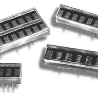
LED DISPLAY 5X7 8CHAR 3.8MM BLUE
Manufacturer
Avago Technologies US Inc.
Series
HCMS-29xxr
Datasheet
1.HCMS-2919.pdf
(14 pages)
Specifications of HCMS-2919
Display Type
Alphanumeric
Millicandela Rating
*
Size / Dimension
1.40" L x 0.40" W x 0.20" H (35.6mm x 10.2mm x 5.1mm)
Color
Blue
Configuration
5 x 7
Voltage - Forward (vf) Typ
*
Package / Case
26-DIP
Number Of Digits/alpha
8
Digit/alpha Size
0.15" (3.8mm)
Number Of Digits
8
Illumination Color
Blue
Wavelength
428 nm
Operating Voltage
5.5 V
Maximum Operating Temperature
+ 85 C
Minimum Operating Temperature
- 40 C
Luminous Intensity
170 ucd
Lead Free Status / RoHS Status
Lead free / RoHS Compliant
Common Pin
-
Lead Free Status / Rohs Status
Details


Appendix A. Thermal Considerations
The display IC has a maximum junction temperature
of 150°C. The IC junction temperature can be calculated
with Equation 1 below.
A typical value for Rθ
for a display mounted in a socket and covered with a
plastic filter. The socket is soldered to a .062 in. thick
PCB with .020 inch wide, one ounce copper traces. PD
can be calculated as Equation 2 below.
Figure 7 shows how to derate the power of one IC
versus ambient temperature. Operation at high
ambient temperatures may require the power per IC
to be reduced. The power consumption can be reduced
by changing either the N, I
Changing V
consumption.
Appendix B. Electrical Considerations
Current Calculations
The peak and average display current requirements
have a significant impact on power supply selection.
The maximum peak current is calculated with Equation
3 below.
The average current required by the display can be
calculated with Equation 4 below.
The power supply has to be able to supply I
transients and supply I
range on V
significantly changing the display brightness.
12
LOGIC
LED
allows noise on this supply without
has very little impact on the power
JA
is 100°C/W. This value is typical
LED
(AVG) continuously. The
PIXEL
, Osc cyc or V
PEAK
LED
.
Figure 7. Maximum power dissipation per IC versus ambient
temperature.
Equation 1:
T
Where:
Equation 2:
P
Where:
Equation 3:
I
Where:
Equation 4:
I
(see Variable Definitions above)
Duty Factor = 1/8 * Osccyc/64
PEAK
LED
J
D
MAX = T
= (N * I
(AVG) = N * I
1.3
1.2
1.1
1.0
0.9
0.8
0.7
0.6
0.5
0.4
0.3
0.2
0.1
Osc cyc = number of ON oscillator cycles per row
= M * 20 * I
T
I
0
I
V
PIXEL
J
I
PEAK
I
MAX = maximum IC junction temperature
LOGIC
LOGIC
25
PIXEL
Rθ
20 = maximum number of LEDs on per IC
M = number of ICs in the system
P
PIXEL
P
T
30
JA
N = number of pixels on (maximum 4 char * 5 * 7 = 140)
A
D
D
A
= maximum instantaneous peak current for the display
= peak current for one LED
+ P
= ambient temperature surrounding the display
= thermal resistance from the IC junction to ambient
= power dissipated by the IC
= total power dissipation
= peak pixel current.
= IC logic current
= logic supply voltage
35
* Duty Factor * V
T
PIXEL
40
A
PIXEL
D
- AMBIENT TEMPERATURE - C
* Rθ
45
* 1/8 * (oscillator cycles)/64
50
JA
55
60
RΘ
LED
65
J-A
) + I
70
= 100 C/W
75
LOGIC
80
85
* V
90
LOGIC
Related parts for HCMS-2919
Image
Part Number
Description
Manufacturer
Datasheet
Request
R

Part Number:
Description:
LED DISPLAY 5X7 4CHAR 5MM GREEN
Manufacturer:
Avago Technologies US Inc.
Datasheet:

Part Number:
Description:
LED DISPLAY 5X7 8CHAR 3.8MM YLW
Manufacturer:
Avago Technologies US Inc.
Datasheet:

Part Number:
Description:
LED DISPLAY 5X7 4CHAR 3.8MM YLW
Manufacturer:
Avago Technologies US Inc.
Datasheet:

Part Number:
Description:
LED DISPLAY 5X7 4CHAR 3.8MM ORN
Manufacturer:
Avago Technologies US Inc.
Datasheet:

Part Number:
Description:
LED DISPL 5X7 4CHAR 3.8MM ALGAAS
Manufacturer:
Avago Technologies US Inc.
Datasheet:
Part Number:
Description:
LED DISPLAY 5X7 4CHAR 3.8MM RED
Manufacturer:
Avago Technologies US Inc.
Datasheet:
Part Number:
Description:
LED DISPLAY 5X7 4CHAR 3.8MM ORN
Manufacturer:
Avago Technologies US Inc.
Datasheet:
Part Number:
Description:
LED DISPLAY 5X7 4CHAR 3.8MM YLW
Manufacturer:
Avago Technologies US Inc.
Datasheet:
Part Number:
Description:
LED DISPLAY 5X7 4CHAR 5MM YLW
Manufacturer:
Avago Technologies US Inc.
Datasheet:
Part Number:
Description:
LED DISPLAY 5X7 4CHAR 5MM ORN
Manufacturer:
Avago Technologies US Inc.
Datasheet:
Part Number:
Description:
LED DISPLAY 5X7 4CHAR 5MM GRN
Manufacturer:
Avago Technologies US Inc.
Datasheet:
Part Number:
Description:
LED DISPLAY 5X7 4CHAR 5MM RED
Manufacturer:
Avago Technologies US Inc.
Datasheet:
Part Number:
Description:
LED DISPLAY 5X7 4CHAR 3.8MM RED
Manufacturer:
Avago Technologies US Inc.
Datasheet:
Part Number:
Description:
LED DISPLAY 5X7 4CHAR 3.8MM GRN
Manufacturer:
Avago Technologies US Inc.
Datasheet:
Part Number:
Description:
LED DISPLAY 5X7 4CHAR 5MM GRN
Manufacturer:
Avago Technologies US Inc.
Datasheet: