HCMS-2976 Avago Technologies US Inc., HCMS-2976 Datasheet - Page 7
HCMS-2976
Manufacturer Part Number
HCMS-2976
Description
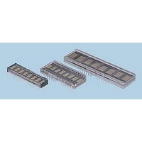
LED DISPLAY 5X7 8CHAR 5MM BLUE
Manufacturer
Avago Technologies US Inc.
Series
HCMS-29xxr
Specifications of HCMS-2976
Millicandela Rating
*
Internal Connection
*
Size / Dimension
1.69" L x 0.45" W x 0.21" H (42.93mm x 11.43mm x 5.33mm)
Color
Blue
Configuration
*
Voltage - Forward (vf) Typ
*
Package / Case
26-DIP
Display Type
Alphanumeric
Number Of Digits/alpha
8
Digit/alpha Size
0.20" (5mm)
Character Format
Dot Matrix
Character Size
5.08mm
Led Color
Blue
Luminous Intensity
170µcd
No. Of Digits / Alpha
8
Display Area Width
42.93mm
Display Area Height
11.43mm
Number Of Digits
8
Illumination Color
Blue
Wavelength
460 nm
Operating Voltage
5.5 V
Maximum Operating Temperature
+ 85 C
Minimum Operating Temperature
- 40 C
Lead Free Status / RoHS Status
Lead free / RoHS Compliant
Common Pin
-
Lead Free Status / Rohs Status
Details


Dot Register
The Dot Register holds the pattern to be displayed by
the LEDs. Data is loaded into the Dot Register according
to the procedure shown in Table 1 and Figure 3.
First RS is brought low, then CE is brought low. Next,
each successive rising CLK edge will shift in the data at
the DIN pin. Loading a logic high will turn the
corresponding LED on; a logic low turns the LED off.
When all 160 bits have been loaded (or 320 bits in an
8-digit display), CE is brought to logic high.
When CLK is next brought to logic low, new data is
latched into the display dot drivers. Loading data into
the Dot Register takes place while the previous data is
displayed and eliminates the need to blank the display
while loading data.
Figure 3. Write Cycle Timing Diagram
7
(SIMULTANEOUS)
D
LED OUTPUTS,
OUT
REGISTERS
(SERIAL)
CONTROL
D
CLK
OUT
D
CE
RS
IN
T
CLKCE
T
3
RSS
1
NOTE:
1. DATA IS COPIED TO THE CONTROL REGISTER OR THE DOT LATCH AND LED OUTPUTS WHEN CE IS HIGH AND CLK IS LOW.
T
T
CEDO
RSH
10
2
T
CES
4
T
9
T
DOUTP
DS
6
T
T
DOUT
DH
7
8
T
11
CLKH
PREVIOUS DATA
T
CLKL
12
Notes:
1. Bit D
2. Selection of Control Word 1 or Control Word 0 is set by D
3. Control Word data is loaded Most Significant Bit (D
Table 1. Register Truth Table
Function
Select Dot Register
Load Dot Register
DIN = HIGH, LED = "ON"
DIN = LOW, LED = "OFF"
Copy Data from Dot
Register to Dot Latch
Select Control Register
Load Control Register
Latch Data to Control Word
for serial mode or High for simultaneous mode.
Control Shift Register. The unselected control word retains its
previous value.
0
of Control Word 1 must have been preciously set to Low
[1,3]
[2]
T
CEH
CLK
Not
Rising
L
Not
Rising
L
↑
↑
5
NEW DATA LATCHED HERE
L
H
L
H
CE
↓
↓
7
) first.
NEW DATA
[1]
7
RS
H
of the
X
X
X
X
Related parts for HCMS-2976
Image
Part Number
Description
Manufacturer
Datasheet
Request
R

Part Number:
Description:
LED DISPLAY 5X7 4CHAR 5MM GREEN
Manufacturer:
Avago Technologies US Inc.
Datasheet:

Part Number:
Description:
LED DISPLAY 5X7 8CHAR 3.8MM YLW
Manufacturer:
Avago Technologies US Inc.
Datasheet:

Part Number:
Description:
LED DISPLAY 5X7 4CHAR 3.8MM YLW
Manufacturer:
Avago Technologies US Inc.
Datasheet:

Part Number:
Description:
LED DISPLAY 5X7 4CHAR 3.8MM ORN
Manufacturer:
Avago Technologies US Inc.
Datasheet:

Part Number:
Description:
LED DISPL 5X7 4CHAR 3.8MM ALGAAS
Manufacturer:
Avago Technologies US Inc.
Datasheet:
Part Number:
Description:
LED DISPLAY 5X7 4CHAR 3.8MM RED
Manufacturer:
Avago Technologies US Inc.
Datasheet:
Part Number:
Description:
LED DISPLAY 5X7 4CHAR 3.8MM ORN
Manufacturer:
Avago Technologies US Inc.
Datasheet:
Part Number:
Description:
LED DISPLAY 5X7 4CHAR 3.8MM YLW
Manufacturer:
Avago Technologies US Inc.
Datasheet:
Part Number:
Description:
LED DISPLAY 5X7 4CHAR 5MM YLW
Manufacturer:
Avago Technologies US Inc.
Datasheet:
Part Number:
Description:
LED DISPLAY 5X7 4CHAR 5MM ORN
Manufacturer:
Avago Technologies US Inc.
Datasheet:
Part Number:
Description:
LED DISPLAY 5X7 4CHAR 5MM GRN
Manufacturer:
Avago Technologies US Inc.
Datasheet:
Part Number:
Description:
LED DISPLAY 5X7 4CHAR 5MM RED
Manufacturer:
Avago Technologies US Inc.
Datasheet:
Part Number:
Description:
LED DISPLAY 5X7 4CHAR 3.8MM RED
Manufacturer:
Avago Technologies US Inc.
Datasheet:
Part Number:
Description:
LED DISPLAY 5X7 4CHAR 3.8MM GRN
Manufacturer:
Avago Technologies US Inc.
Datasheet:
Part Number:
Description:
LED DISPLAY 5X7 4CHAR 5MM GRN
Manufacturer:
Avago Technologies US Inc.
Datasheet: