SCD5582A OSRAM Opto Semiconductors Inc, SCD5582A Datasheet - Page 8
SCD5582A
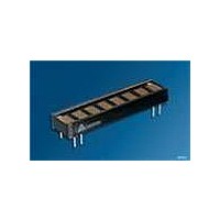
Manufacturer Part Number
SCD5582A
Description
DISPLAY 8CHAR .145" 5X5 HE RED
Manufacturer
OSRAM Opto Semiconductors Inc
Series
Intelligent Display®r
Datasheet
1.SCD5584A.pdf
(17 pages)
Specifications of SCD5582A
Millicandela Rating
265µcd
Size / Dimension
1.50" L x 0.39" W x 0.20" H (38.10mm x 10.00mm x 5.08mm)
Color
Red
Configuration
5 x 5
Lead Free Status / RoHS Status
Lead free / RoHS Compliant
Voltage - Forward (vf) Typ
-
Internal Connection
-
Lead Free Status / Rohs Status
Details
Other names
Q68100A0997


The following explains how to format the serial data to be loaded
into the display. The user supplies a string of bit mapped decoded
characters. The contents of this string is shown in Figure „Loading
Serial Character Data a“ (page 8). Figure „Loading Serial Charac-
ter Data b“ (page 8) shows that each character consist of six 8 bit
words. The first word encodes the display character location and
the succeeding five bytes are row data. The row data represents
the status (On, Off) of individual column LEDs. Figure „Loading
Serial Character Data c“ (page 8) shows that each 8 bit word is
formatted to include a three bit Operational Code (OPCODE)
defined by bits D7–D5 and five bits (D4–D0) representing Column
Data, Character Address, or Control Word Data.
Figure „Loading Serial Character Data d“ (page 8) shows the
sequence for loading the bytes of data. Bringing the LOAD line low
enables the serial register to accept data. The shift action occurs
on the low to high transition of the serial data clock (SDCLK). The
least significant bit (D0) is loaded first. After eight clock pulses the
LOAD line is brought high. With this transition the OPCODE is
decoded. The decoded OPCODE directs D4–D0 to be latched in
the Character Address register, stored in the RAM as Column
data, or latched in the Control Word register. The control IC
requires a minimum 600 ns delay between successive byte loads.
As indicated in Figure „Loading Serial Character Data a“ (page 8),
a total of 528 bits of data are required to load all eight characters
into the display.
Loading Serial Character Data
2006-01-23
a.
b.
c.
d.
Character 0
Character 0
Address
D0
Character Address
0
LOAD
Serial
Clock
DATA
D1
0
Character 1
11 Clock Cycles, 2.2 µs
SCD5580A, SCD5581A, SCD5582A, SCD5583A, SCD5584A
D2
0
D3
0
Row 0 Column
Example: Serial Clock = 5 MHz, Clock Period = 200 ns
t 0
Clock
Period
66 Clock Cycles, 13.2 µs
D4
D0
Data
0
Character 2
D5
1
OPCODE
D1
D6
0
528 Clock Cycles, 105.6 µs
D7
Row 1 Column
1
D2
Character 3
600 ns(min.)
Data
Between
Loads
Time
D3
8
D5
D4
The Character Address Register bits, D4–D0 (Table „Load Charac-
ter Address“ (page 9)) and Row Address Register bits, D7–D5
(Table „Load Column Data“ (page 9)) direct the Column Data bits,
D4–D0 (Table „Load Column Data“ (page 9)) to specific RAM loca-
tion. Table „Character ’D’“ (page 8) shows the Row Address for the
example character “D.” Column data is written and read asynchro-
nously from the 200 bit RAM. Once loaded the internal oscillator
and character multiplexer reads the data from the RAM. These
characters are row strobed with column data as shown in Figures
„Row and Column Location“ (page 9) and „Row Strobing“
(page 10). The character strobe rate is determined by the internal
or user supplied external MUX Clock and the IC’s ÷320 counter.
Character “D”
Row 0
Row 1
Row 2
Row 3
Row 4
D0
C4
Row 2 Column
Character 4
Column Data
11 Clock Cycles, 2.2 µs
D5
Data
D1
C3
D2
C2
D6
Op code
D7
0
0
0
0
1
D3
C1
Character 5
D6 D5
0
0
1
1
0
Row 3 Column
D7
D4
C0
0
1
0
1
0
Data
D5 D6 D7
Time between LOADS
OPCODE
Character 6
Column Data
D4
C0
1
1
1
1
1
Row 4 Column
600 ns(min.)
D3
C1
1
0
0
0
1
Between
Loads
Data
Time
D2
C2
1
0
0
0
1
Character 7
D1
C3
1
0
0
0
1
D0
C4
0
1
1
1
0
Hex
1E
31
51
71
9E
Related parts for SCD5582A
Image
Part Number
Description
Manufacturer
Datasheet
Request
R

Part Number:
Description:
INTELLIGENT DISP 4CHAR 5X7 HERED
Manufacturer:
OSRAM Opto Semiconductors Inc
Datasheet:

Part Number:
Description:
DISPLAY 8DIGIT CERAMIC GREEN
Manufacturer:
OSRAM Opto Semiconductors Inc
Datasheet:

Part Number:
Description:
EMITTER IR 950NM 5MM SMD RADIAL
Manufacturer:
OSRAM Opto Semiconductors Inc
Datasheet:

Part Number:
Description:
LED TOPLED GREEN 570NM 2-PLCC
Manufacturer:
OSRAM Opto Semiconductors Inc
Datasheet:

Part Number:
Description:
INTERRUPTER RELFECT W/FILTR SMD
Manufacturer:
OSRAM Opto Semiconductors Inc
Datasheet:

Part Number:
Description:
LED Displays 5x7 Green 0.145 , 4-CHARACTER
Manufacturer:
OSRAM Opto Semiconductors Inc
Datasheet:

Part Number:
Description:
Q65110A4321_SIDELED PURE GREEN EOL150407
Manufacturer:
OSRAM Opto Semiconductors Inc
Datasheet:
Part Number:
Description:
Q65110A1202_RO DETECTOR 3/5MM_TR_RO
Manufacturer:
OSRAM Opto Semiconductors Inc
Datasheet:

Part Number:
Description:
PHOTODIODE 900NM 3MM W/FILTER
Manufacturer:
OSRAM Opto Semiconductors Inc
Datasheet:
Part Number:
Description:
INTELLIGENT DISP 4CHAR 5X7 HERED
Manufacturer:
OSRAM Opto Semiconductors Inc
Datasheet:
Part Number:
Description:
LED TOPLED GREEN 570NM 2-PLCC
Manufacturer:
OSRAM Opto Semiconductors Inc
Datasheet:
Part Number:
Description:
PHOTODIODE 900NM 3MM W/FILTER
Manufacturer:
OSRAM Opto Semiconductors Inc
Datasheet:

Part Number:
Description:
PHOTODIODE 850NM THRU-HOLE
Manufacturer:
OSRAM Opto Semiconductors Inc
Datasheet:

Part Number:
Description:
PHOTODIODE 880NM W/FILTER SMD
Manufacturer:
OSRAM Opto Semiconductors Inc
Datasheet: