ISD2352 OSRAM Opto Semiconductors Inc, ISD2352 Datasheet
ISD2352
Specifications of ISD2352


Related parts for ISD2352


ISD2352 Summary of contents
Page 1
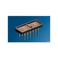
Dot Matrix / Serial Input Alphanumeric Industrial Display Sunlight Viewable: ISD235X ISD201X, ISD231X, ISD235X ISD201X RoHS Compliant - By ExemptionDESCRIPTION The ISD201X/231X/235X are four digit dot matrix serial input alphanumeric displays. The displays ...
Page 2
... Ordering Information Type ISD2351 ISD2352 ISD2353 ISD2010 ISD2011 ISD2012 ISD2013 ISD2310 ISD2311 ISD2312 ISD2313 Maximum Ratings Parameter Operating temperature range Storage temperature range Supply voltage V to GND CC Inputs, data out and V B Column input voltage Solder temperature 1.59 mm (0.063“) below seating plane, t < 5.0 s ...
Page 3
Timing Characteristics CLOCK DATA IN DATA OUT DISPLAY AC Electrical Characteristics (V = 4. –55°C to 100° Symbol Description T Setup Time SETUP T Hold Time HOLD T Clock Width Low WL ...
Page 4
ISD201X Package Outlines Pin 1 Indicator Year Work Week Seating Plane 1.27 (0.050) 12 pl. 4.44 (0.175) Pin 1 marked by dot on back of package 2006-04-04 Hue Code ISD201X Luminous Intensity Code OSRAM Part Number 0.51 (0.020) ±0.08 ...
Page 5
ISD231X / ISD235X Package Outlines: Dimensions in mm (inch) Pin 1 indicators dot and notch on package underside Year Work Week 1.27 (0.050) 12 pl. 5 (0.197) 2.51 (0.099) ±0.13 (0.005) Tolerance: ±0.30 (0.015) 2006-04-04 Hue Code ISD231X Luminous ...
Page 6
Maximum Allowable Power Dissipation vs. Temperature, ISD201X 1 0 ˚C/W thJA ˚C/W thJA 0.6 0.4 0 125 ˚C jmax 0 -60 -40 - Maximum ...
Page 7
... Dominant Wavelength Yellow ISD2011 / ISD2311 / ISD2351 Description Peak Luminous Intensity per LED (Character Average) Peak Wavelength 8) Dominant Wavelength High Efficiency Red ISD2012 / ISD2312 / ISD2352 Description Peak Luminous Intensity per LED (Character Average) Peak Wavelength 8) Dominant Wavelength High Efficiency Green ISD2013 / ISD2313 / ISD2353 ...
Page 8
Recommended Operating Conditions (Guaranteed over operating temperature range) Parameter Supply Voltage Data Out Current, Low State Data Out Current, High State Column Input Voltage, Column On Setup Time Hold Time Width of Clock Clock Frequency Clock Transition Time Free Air ...
Page 9
Electrical Characteristics (–55°C to +100°C, unless otherwise specified) Description Supply Current (quiescent) Supply Current (operating) Column Current at Any Column Input* Column Current at Any Column Input* ISD2010 red ISD2011/2/3: yellow, HER, green ISD231X: red, yellow, HER, green ISD235X: yellow, ...
Page 10
Block Diagram Blanking Control, Rows Serial Data Input Clock Contrast Enhancement Filters for Sunlight Readability Display Color Filter Color Red, HER Red Yellow Amber ...
Page 11
The small alphanumeric displays are hybrid LED and CMOS assemblies that are designed for reliable operation in commercial and industrial environments. Optimum reliability and optical performance will result when the junction temperature of the LEDs and CMOS ICs are kept ...
Page 12
Normalized Luminous Intensity vs. Junction Temperature 1 10 Normalized to ˚ -60 -40 - 100 ˚C 140 When mounted in a 10°C/W socket and operated at Absolute ...
Page 13
Package Power Dissipation, ISD201X 1 3 COL COL 20 ˚C A 1.0 0 ...
Page 14
Character Power Dissipation, ISD201X 0 3.5 V, COL 0.3 Duty Factor = 20% 0.2 0 LEDs on per ...
Page 15
Revision History: 2006-04-04 Previous Version: 2004-12-09 Page Subjects (major changes since last revision) all RoHS Compliant - By Exemption Attention please! The information describes the type of component and shall not be considered as assured characteristics. Terms of delivery and ...
Page 16
Remarks: 1) Operation above +100°C ambient is possible if the following conditions are met. The junction should not exceed T should not exceed TC=100°C. 2) Maximum allowable dissipation is derived from: V =5. =2 =3.5 V ...