ISD2352 OSRAM Opto Semiconductors Inc, ISD2352 Datasheet - Page 11
ISD2352
Manufacturer Part Number
ISD2352
Description
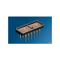
DISPLAY 4CHAR .200" HI EFF RED
Manufacturer
OSRAM Opto Semiconductors Inc
Datasheet
1.ISD2010.pdf
(16 pages)
Specifications of ISD2352
Millicandela Rating
2500µcd
Size / Dimension
0.79" L x 0.33" W x 0.10" H (20.07mm x 8.43mm x 2.54mm)
Color
Red
Configuration
5 x 7
Number Of Digits
4
Character Size
0.2 in
Illumination Color
High Efficiency Red
Wavelength
630 nm
Maximum Operating Temperature
+ 100 C
Minimum Operating Temperature
- 55 C
Luminous Intensity
2500 ucd
Viewing Area (w X H)
2.11 mm x 5.08 mm
Display Type
5 x 7 Dot Matrix
Lead Free Status / RoHS Status
Lead free / RoHS Compliant
Voltage - Forward (vf) Typ
-
Internal Connection
-
Lead Free Status / Rohs Status
Details
Other names
Q68000A8143


The small alphanumeric displays are hybrid LED and CMOS
assemblies that are designed for reliable operation in commercial
and industrial environments. Optimum reliability and optical
performance will result when the junction temperature of the LEDs
and CMOS ICs are kept as low as possible.
Thermal Modeling
ISD displays consist of two driver ICs and four 5 x 7 LED matrixes.
A thermal model of the display is shown in Figure „Thermal Model“.
It illustrates that the junction temperature of the semiconductor =
junction self heating + the case temperature rise + the ambient
temperature.
Equation 1 shows this relationship.
Thermal Model
See Equation 1 below.
The junction rise within the LED is the product of the thermal
impedance of an individual LED (37°C/W, DF=20%, F=200 Hz),
times the forward voltage, V
13 – 14.5 mA. This rise averages T
shows the V
Model Number
The junction rise within the LED driver IC is the combination of the
power dissipated by the IC quiescent current and the 28 row driver
current sinks. The IC junction rise is given in Equation 2.
Equation 1.
Equation 2.
2006-04-04
T
ISD2010
ISD2310
ISD2011/2/3
ISD2311/2/3
ISD2351/2/3
T J LED
LED Power
J IC
T
T
(
LED
(
J LED
J IC
R
(
(
θ
1
T
)
1
)
=
)
=
F(LED)
=
)
[
IC Power
5 V
P LED Z θJ C
IC
=
P
(
R
COL
θ2
T
for the respective displays.
[
2
COL
(
I
COL
VF
Min.
1.6
1.9
(
LED Power
R
–
LED
θJC
R
V
⁄
θ1
28
F(LED)
F LED
T
+
1
(
+
)V
P CASE R θJC
R
, and forward current I
LED Power
F LED
R
θCA
LED
θ
(
CA
R
J(LED)
)
Typ.
1.7
2.2
θ
)
1
T
⋅
)
1
(
(
=1°C. The Table below
+
I
)
COL
T
Z
IC Power
A
θJC
IC
R
θ
T
+
2
2 ⁄
2
R θCA
]
)
Max.
2.0
3.0
+
⋅
LED Power
[
(
F
(
n 35
LED
(LED), of
n 35
R
) T A
⁄
+
IDDG5321
⁄
1 θ
T
1
)DF
)I
COL
11
+
V
A thermal resistance of 28°C/W results in a typical junction rise of
6°C.
See Equation 2 below.
For ease of calculations the maximum allowable electrical operat-
ing condition is dependent upon the aggregate thermal resistance
of the LED matrixes and the two driver ICs. All of the thermal man-
agement calculations are based upon the parallel combination of
these two networks which is 15°C/W. Maximum allowable power
dissipation is given in Equation 3.
Equation 3.
For further reference see Figures „Maximum Allowable Power Dis-
sipation vs. Temperature“ (page 6) and Figures from page 12 on.
Key to equation symbols
DF
I
I
n
P
P
P
P
R
R
T
T
T
T
V
V
V
Z
Optical Considerations
The light output of the LEDs is inversely related to the LED diode’s
junction temperature as shown in „Normalized Luminous Intensity
vs. Junction Temperature“ (page 12). For optimum light output,
keep the thermal resistance of the socket or PC board as low as
possible.
CC
COL
DF 5V
CC
A
CASE
COL
DISPLAY
LED
J(IC)
J(LED)
J(MAX)
CC
COL
F(LED)
qJC
qCA
qJC
P
P
DISPLAY
DISPLAY
(
⋅
I
CC
COL
]
⋅
[
R
)
ISD201X, ISD231X, ISD235X
=
=
Duty factor
Quiescent IC current
Column current
Number of LEDs on in a 5 x 7 array
Package power dissipation excluding LED
under consideration
Power dissipation of a column
Power dissipation of the display
Power dissipation of a LED
Thermal resistance case to ambient
Thermal resistance junction to case
Ambient temperature
Junction temperature of an IC
Junction temperature of a LED
Maximum junction temperature
IC voltage
Column voltage
Forward voltage of LED
Thermal impedance junction to case
+
θJC
V
T
--------------------------------------- -
5V
R
CC
J MAX
θJC
+
(
COL
R
I
θCA
CC
+
R
)
I
]
θCA
COL
–
]
⋅
[
+
T
R
A
T
θJC
A
(
n 35
⁄
+
R
) DF
θCA
+
]
+
V
CC
T
A
I
CC
Related parts for ISD2352
Image
Part Number
Description
Manufacturer
Datasheet
Request
R

Part Number:
Description:
INTELLIGENT DISP 4CHAR 5X7 HERED
Manufacturer:
OSRAM Opto Semiconductors Inc
Datasheet:

Part Number:
Description:
DISPLAY 8DIGIT CERAMIC GREEN
Manufacturer:
OSRAM Opto Semiconductors Inc
Datasheet:

Part Number:
Description:
EMITTER IR 950NM 5MM SMD RADIAL
Manufacturer:
OSRAM Opto Semiconductors Inc
Datasheet:

Part Number:
Description:
LED TOPLED GREEN 570NM 2-PLCC
Manufacturer:
OSRAM Opto Semiconductors Inc
Datasheet:

Part Number:
Description:
INTERRUPTER RELFECT W/FILTR SMD
Manufacturer:
OSRAM Opto Semiconductors Inc
Datasheet:

Part Number:
Description:
LED Displays 5x7 Green 0.145 , 4-CHARACTER
Manufacturer:
OSRAM Opto Semiconductors Inc
Datasheet:

Part Number:
Description:
Q65110A4321_SIDELED PURE GREEN EOL150407
Manufacturer:
OSRAM Opto Semiconductors Inc
Datasheet:
Part Number:
Description:
Q65110A1202_RO DETECTOR 3/5MM_TR_RO
Manufacturer:
OSRAM Opto Semiconductors Inc
Datasheet:

Part Number:
Description:
PHOTODIODE 900NM 3MM W/FILTER
Manufacturer:
OSRAM Opto Semiconductors Inc
Datasheet:
Part Number:
Description:
INTELLIGENT DISP 4CHAR 5X7 HERED
Manufacturer:
OSRAM Opto Semiconductors Inc
Datasheet:
Part Number:
Description:
LED TOPLED GREEN 570NM 2-PLCC
Manufacturer:
OSRAM Opto Semiconductors Inc
Datasheet:
Part Number:
Description:
PHOTODIODE 900NM 3MM W/FILTER
Manufacturer:
OSRAM Opto Semiconductors Inc
Datasheet:

Part Number:
Description:
PHOTODIODE 850NM THRU-HOLE
Manufacturer:
OSRAM Opto Semiconductors Inc
Datasheet:

Part Number:
Description:
PHOTODIODE 880NM W/FILTER SMD
Manufacturer:
OSRAM Opto Semiconductors Inc
Datasheet: