TORX141 Toshiba, TORX141 Datasheet
TORX141
Specifications of TORX141
Available stocks


Related parts for TORX141

TORX141 Summary of contents
Page 1
... Note 1: Soldering time < seconds. (More than 1 mm apart from package) Recommended Operating Conditions Characteristics Supply voltage FIBER OPTIC RECEIVING MODULE TORX141 Symbol Rating Unit - °C stg T - °C opr V -0 260 T °C sol (Note 1) Symbol Min Typ. Max V 2.7 3 TORX141 Unit 3.6 V 2001-10-03 Unit: mm ...
Page 2
... Low level output voltage Note 2: High level output when optical flux is received. Low level output when optical flux is not received. The duty factor must be kept 25 to 75%. Note 3: All Plastic Fiber (970/1000 mm). Note 4: Between input of TOTX141 and output of TORX141. −9 Note 5: BER < peak value. ...
Page 3
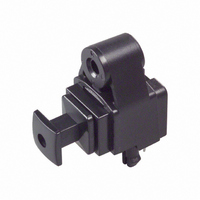
... Support pins The TORX141 has support pins in order to fix itself to the PCB temporary. Please make the hole for these pins in the PCB under the condition for described in board layout hole pattern. (for reference) Unit: mm Tolerance: ± ...
Page 4
... Panel attachment TORX141 has hole for panel attachment. Please be sure to attach it to panel with self-tapping screw. (7) Solvent When using solvent for flux removal, do not use a high acid or high alkali solvent. Be careful not to pour solvent in to the optical connector ports. If solvent is inadvertently poured in to them, clean it off using cotton tips ...
Page 5
... TOSHIBA CORPORATION for any infringements of intellectual property or other rights of the third parties which may result from its use. No license is granted by implication or otherwise under any intellectual property or other rights of TOSHIBA CORPORATION or others. · The information contained herein is subject to change without notice. 5 TORX141 000707EAC 2001-10-03 ...