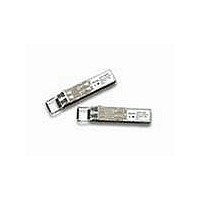
AFBR-5715LZ Avago Technologies US Inc., AFBR-5715LZ Datasheet - Page 10

AFBR-5715LZ
Manufacturer Part Number
AFBR-5715LZ
Description
TXRX OPTICAL SFP DMI STD LATCH
Manufacturer
Avago Technologies US Inc.
Specifications of AFBR-5715LZ
Data Rate
1.25Gbps
Wavelength
850nm
Applications
Ethernet
Voltage - Supply
3.135 V ~ 3.465 V
Connector Type
LC Duplex
Mounting Type
SFP
Function
Designed for those applications requiring DMI features.
Product
Transceiver
Maximum Rise Time
0.26 ns/0.22 ns (Typ)
Maximum Fall Time
0.26 ns/0.22 ns (Typ)
Pulse Width Distortion
0.227 ns (Max)/0.266 ns (Max)
Operating Supply Voltage
3.135 V to 3.465 V
Maximum Operating Temperature
+ 85 C
Minimum Operating Temperature
- 10 C
Package / Case
SFP
Optical Fiber Type
TX/RX
Data Transfer Rate
1250MBd
Optical Rise Time
0.26/0.22ns
Optical Fall Time
0.26/0.22ns
Jitter
0.227/0.266ns
Operating Temperature Classification
Commercial
Peak Wavelength
850nm
Package Type
SFP
Operating Supply Voltage (min)
3.135V
Operating Supply Voltage (typ)
3.3V
Operating Supply Voltage (max)
3.465V
Operating Temp Range
-10C to 85C
Mounting
Snap Fit To Panel
Pin Count
20
Lead Free Status / RoHS Status
Lead free / RoHS Compliant
Lead Free Status / RoHS Status
Lead free / RoHS Compliant, Lead free / RoHS Compliant
Table 6. Transmitter Optical Characteristics
Figure 5a. Gigabit Ethernet transmitter eye mask diagram
Table 7. Receiver Optical Characteristics
10
Notes:
1. 50/125 µm fiber with NA = 0.2, 62.5/125 µm fiber with NA = 0.275.
Parameter
Optical Input Power
Receiver Sensitivity
(Optical Input Power)
Stressed Receiver Sensitivity
(TP3 to TP4 Contribution 1.25GBd)
Return Loss
LOS De-Asserted
LOS Asserted
LOS Hysterisis
Parameter
Output Optical Power (Average)
Optical Extinction Ratio
Center Wavelength
Spectral Width - rms
Optical Rise/Fall Time
Relative Intensity Noise
Pout TX_DISABLE Assorted
Total Jitter
Total Jitter
(TP1 to TP2 Contribution
130
100
–20
80
50
20
0
0
0
NORMALIZED TIME (% OF UNIT INTERVAL)
NORMALIZED TIME (UNIT INTERVAL)
0.22
22
0.375
37.5
0.625
62.5
Symbol
P
P
P
P
P
TJ
R
RMIN
D
A
D
0.78
-P
78
A
Symbol
P
ER
RIN
P
λ
σ
T
TJ
OUT
RISE
OFF
C
/
FALL
1.0
100
1.30
1.00
0.80
0.50
0.20
0
–0.20
Minimum
-17
-
-30
Minimum
-9.5
9
830
Figure 5b. Typical AFBR-571xZ eye mask diagram
-21
Typical
3
-6.5
12
850
150
Typical
Maximum
0
-17
-12.5
-13.5
266
0.332
-12
-17
Maximum
-3
860
0.85
260
-117
227
0.284
-35
Unit
dBm
dBm
dBm
dBm
ps
UI
dB
dBm
dBm
dB
Unit
dBm
dB
nm
nm
ps
dB/Hz
ps
UI
dBm
Notes
62.5/125 µm fiber
50/125 µm fiber
1
Notes


