AFCT-5715PZ Avago Technologies US Inc., AFCT-5715PZ Datasheet - Page 4
AFCT-5715PZ
Manufacturer Part Number
AFCT-5715PZ
Description
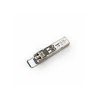
TXRX OPT SFF PLUGGABLE BAIL DMI
Manufacturer
Avago Technologies US Inc.
Series
-r
Datasheet
1.AFCT-5710LZ.pdf
(19 pages)
Specifications of AFCT-5715PZ
Data Rate
1.25Gbd
Wavelength
1310nm
Applications
Ethernet
Voltage - Supply
3.14 V ~ 3.47 V
Connector Type
LC Duplex
Mounting Type
SFP
Function
SFP Optical Transceivers with Optional DMI for Gigabit Ethernet 1.25 GBd. Intended for premise, public and access networking applications.
Product
Transceiver
Maximum Rise Time
0.26 ns/0.4 ns
Maximum Fall Time
0.26 ns/0.4 ns
Pulse Width Distortion
0.227 ns (Max)/0.267 ns (Max)
Operating Supply Voltage
3.14 V to 3.47 V
Maximum Operating Temperature
+ 85 C
Minimum Operating Temperature
- 10 C
Package / Case
SFP
Data Rate Max
1.25Gbps
Supply Current
200mA
Supply Voltage
3.3V
Data Transmission Distance
10km
Wavelength Typ
1.31µm
Power Rating
660mW
Peak Reflow Compatible (260 C)
No
Leaded Process Compatible
No
Rohs Compliant
Yes
Lead Free Status / RoHS Status
Lead free / RoHS Compliant
For Use With
Singlemode Glass
Lead Free Status / RoHS Status
Lead free / RoHS Compliant, Lead free / RoHS Compliant
Available stocks
Company
Part Number
Manufacturer
Quantity
Price
Company:

Part Number:
AFCT-5715PZ
Manufacturer:
Avago Technologies
Quantity:
135


TX_FAULT
A laser fault or a low VCC condition will activate the
transmitter fault signal, TX_FAULT, and disable the
laser. This signal is an open collector output (pull-up
required on the host board); A low signal indicates
normal laser operation and a high signal indicates a
fault. The TX_FAULT will be latched high when a laser
fault occurs and is cleared by toggling the TX_DISABLE
input or power cycling the transceiver. The TX_FAULT is
not latched for Low VCC. The transmitter fault condition
can also be monitored via the two-wire serial interface
(address A2h, byte 110, bit 2).
Eye Safety Circuit
Under normal operating conditions, the laser power
will be maintained below the eye-safety limit. If the
eye safety limit is exceeded at any time, a laser fault will
occur and the TX_FAULT output will be activated.
Receiver Section
The receiver section for the AFCT-571 Z contains an
InGaAs/InP photo detector and a preamplifier mounted
in an optical subassembly. This optical subassembly is
coupled to a post amplifier/decision circuit on a circuit
board. The design of the optical subassembly provides
better than 12 dB Optical Return Loss (ORL).
Connection to the receiver is provided via a LC optical
connector.
RX_LOS
The receiver section contains a loss of signal (RX_LOS)
circuit to indicate when the optical input signal power
is insufficient for Gigabit Ethernet compliance. A high
signal indicates loss of modulated signal, indicating
link failure such as a broken fiber or a failed transmit-
ter. RX_LOS can be also be monitored via the two-wire
serial (address A2h, byte 110, bit 1).
Figure 4. MSA required power supply filter
4
SFP MODULE
V
V
CC
CC
T
R
0.1 μF
0.1 μF
HOST BOARD
10 μF
1 μH
1 μH
0.1 μF
10 μF
3.3 V
Functional Data I/O
Avago’s AFCT-571 Z transceiver is designed to accept
industry standard differential signals. The transceiv-
er provides an AC-coupled, internally terminated
data interface. Bias resistors and coupling capacitors
have been included within the module to reduce the
number of components required on the customer’s
board. Figure 2 illustrates the recommended interface
circuit.
Digital Diagnostic Interface and Serial Identification
The AFCT-571 Z family complies with the SFF-8074i
specification, which defines the module’s serial identi-
fication protocol to use the 2-wire serial CMOS EEPROM
protocol of the ATMEL AT24C01A or similar. Standard
SFP EEPROM bytes 0-255 are addressed per SFF-8074i
at memory address 0xA0 (A0h).
As an enhancement to the conventional SFP interface
defined in SFF-8074i, the AFCT-5715Z is also compliant
to SFF-8472 (the digital diagnostic interface for SFP).
This enhancement adds digital diagnostic monitoring
to standard SFP functionality, enabling failure predic-
tion, fault isolation, and component monitoring capa-
bilities.
Using the 2-wire serial interface, the AFCT-5715Z
provides real time access to transceiver internal supply
voltage and temperature, transmitter output power,
laser bias current and receiver average input power,
allowing a host to predict system compliance issues.
These five parameters are internally calibrated, per the
MSA. New digital diagnostic information is accessed
per SFF-8472 using EEPROM bytes 0-255 at memory
address 0xA2 (A2h).
The digital diagnostic interface also adds the ability
to disable the transmitter (TX_DISABLE), monitor for
Transmitter Faults (TX_FAULT) and monitor for Receiver
Loss of Signal (RX_LOS).
Contents of the MSA-compliant serial ID memory are
shown in Tables 10 through 14. The SFF-8074i and
SFF-8472 specifications are available from the SFF
Committee at http://www.sffcommittee.org.
Predictive Failure Identification
The diagnostic information allows the host system
to identify potential link problems. Once identified, a
fail-over technique can be used to isolate and replace
suspect devices before system uptime is impacted.
Related parts for AFCT-5715PZ
Image
Part Number
Description
Manufacturer
Datasheet
Request
R

Part Number:
Description:
TXRX OPT 1X9 155MB/S 1300NM BK
Manufacturer:
Avago Technologies US Inc.
Datasheet:

Part Number:
Description:
TXRX OPT SFF PLUGGABLE BAIL
Manufacturer:
Avago Technologies US Inc.
Datasheet:

Part Number:
Description:
TXRX 125MBD DUPLEX BLACK SC 1X9
Manufacturer:
Avago Technologies US Inc.
Datasheet:
Part Number:
Description:
TXRX 125MBD DUPLEX BLUE SC 1X9
Manufacturer:
Avago Technologies US Inc.
Datasheet:

Part Number:
Description:
TXRX OPT SM 155MBS SONET OC3/SDH
Manufacturer:
Avago Technologies US Inc.
Datasheet:
Part Number:
Description:
TXRX SFF SM OC3/STM-1 BAIL DMI
Manufacturer:
Avago Technologies US Inc.
Datasheet:
Part Number:
Description:
TXRX 125MBD DUPLEX BLACK SC 1X9
Manufacturer:
Avago Technologies US Inc.
Datasheet:
Part Number:
Description:
TXRX 125MBD DUPLEX BLUE SC 1X9
Manufacturer:
Avago Technologies US Inc.
Datasheet:

Part Number:
Description:
TXRX OPT SM 155MBS SONET OC3/SDH
Manufacturer:
Avago Technologies US Inc.
Datasheet:

Part Number:
Description:
TXRX OPT SM 155MBS SONET OC3/SDH
Manufacturer:
Avago Technologies US Inc.
Datasheet:

Part Number:
Description:
OPTOCOUPLER GATE DRV 2A 16-SOIC
Manufacturer:
Avago Technologies US Inc.
Datasheet:
Part Number:
Description:
OPTOCOUPLER 2CH 2.5A 16-SOIC
Manufacturer:
Avago Technologies US Inc.
Datasheet:

Part Number:
Description:
OPTOCOUPLER GATE DRV 0.4A 16SOIC
Manufacturer:
Avago Technologies US Inc.
Datasheet:

Part Number:
Description:
OPTOCOUPLER 2.0A 250KHZ 8-DIP
Manufacturer:
Avago Technologies US Inc.
Datasheet:

Part Number:
Description:
OPTOCOUPLER 2.0A 250KHZ GW 8-SMD
Manufacturer:
Avago Technologies US Inc.
Datasheet: