AFCT-57R5APZ Avago Technologies US Inc., AFCT-57R5APZ Datasheet - Page 4
AFCT-57R5APZ
Manufacturer Part Number
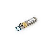
AFCT-57R5APZ
Description
TXRX OPT SFP LC 4/2/1GBD LC CONN
Manufacturer
Avago Technologies US Inc.
Series
-r
Datasheet
1.AFCT-57R5APZ.pdf
(20 pages)
Specifications of AFCT-57R5APZ
Data Rate
4.25Gbps
Wavelength
1310nm
Applications
General Purpose
Voltage - Supply
2.97 V ~ 3.63 V
Connector Type
LC Duplex
Mounting Type
SFP
Function
Digital Diagnostic Optical Transceiver, supports high-speed singlemode optical fiber at signaling rates up to 4.25 Gb/s
Product
Transceiver
Maximum Rise Time
0.9 ns/0.15 ns
Maximum Fall Time
0.9 ns/0.15 ns
Pulse Width Distortion
0.06 ns (Max)/0.061 ns (Max)
Operating Supply Voltage
2.97 V to 3.63 V
Maximum Operating Temperature
+ 85 C
Minimum Operating Temperature
- 10 C
Package / Case
SFP
Lead Free Status / RoHS Status
Lead free / RoHS Compliant
For Use With
Singlemode Glass
Lead Free Status / RoHS Status
Lead free / RoHS Compliant, Lead free / RoHS Compliant


Receiver Section
The receiver section includes the Receiver Optical Sub-
Assembly (ROSA) and the amplification/quantization
circuitry. The ROSA, containing a PIN photodiode and
custom transimpedance amplifier, is located at the optical
interface and mates with the LC optical connector. The
ROSA output is fed to a custom IC that provides post-
amplification and quantization.
Receiver Loss of Signal (Rx_LOS)
The post-amplification IC also includes transition
detection circuitry which monitors the ac level of
incoming optical signals and provides a TTL/CMOS
compatible status signal to the host (pin 8). An adequate
optical input results in a low Rx_LOS output while a high
Rx_LOS output indicates an unusable optical input. The
Rx_LOS thresholds are factory set so that a high output
indicates a definite optical fault has occurred. Rx_LOS
can also be monitored via the two-wire serial interface
(address A2h, byte 110, bit 1).
Functional Data I/O
The AFCT-57R5APZ interfaces with the host circuit board
through twenty I/O pins (SFP electrical connector) iden-
tified by function in Table 2. The board layout for this
interface is depicted in Figure 6.
The AFCT-57R5APZ high speed transmit and receive
interfaces require SFP MSA compliant signal lines on
the host board. To simplify board requirements, biasing
resistors and ac coupling capacitors are incorporated into
the SFP transceiver module (per SFF-8074i) and hence are
not required on the host board. The Tx_Disable, Tx_Fault,
and Rx_LOS require TTL lines on the host board (per
SFF-8074i) if used. If an application chooses not to take
advantage of the functionality of these pins, care must be
taken to ground Tx_Disable (for normal operation).
Figure 2 depicts the recommended interface circuit to
link the AFCT-57R5APZ to supporting physical layer ICs.
Timing for MSA compliant control signals implemented
in the transceiver are listed in Figure 4.
Application Support
An Evaluation Kit and Reference Designs are available to
assist in evaluation of the AFCT-57R5APZ. Please contact
your local Field Sales representative for availability and
ordering details.
4
Caution
There are no user serviceable parts nor maintenance
requirements for the AFCT-57R5APZ. All mechanical
adjustments are made at the factory prior to shipment.
Tampering with, modifying, misusing or improp-
erly handling the AFCT-57R5APZ will void the product
warranty. It may also result in improper operation and
possibly overstress the laser source. Performance deg-
radation or device failure may result. Connection of
the AFCT-57R5APZ to a light source not compliant with
ANSI FC-PI or IEEE 802.3 specifications, operating above
maximum operating conditions or in a manner inconsis-
tent with it’s design and function may result in exposure
to hazardous light radiation and may constitute an act
of modifying or manufacturing a laser product. Persons
performing such an act are required by law to re-certify
and re-identify the laser product under the provisions of
U.S. 21 CFR (Subchapter J) and TUV.
Ordering Information
Please contact your local field sales engineer or one of
Avago Technologies franchised distributors for ordering
information. For technical information, please visit Avago
Technologies’ WEB page at www.avagotech.com or
contact Avago Technologies Semiconductor Products
Customer Response Center at 1-800-235-0312. For infor-
mation related to SFF Committee documentation visit
www.sffcommittee.org.
Regulatory Compliance
The AFCT-57R5APZ complies with all applicable laws
and regulations as detailed in Table 1. Certification level
is dependent on the overall configuration of the host
equipment. The transceiver performance is offered as a
figure of merit to assist the designer.
Electrostatic Discharge (ESD)
The AFCT-57R5APZ is compatible with ESD levels found
in typical manufacturing and operating environments
as described in Table 1. In the normal handling and oper-
ation of optical transceivers, ESD is of concern in two
circumstances.
The first case is during handling of the transceiver prior
to insertion into an SFP compliant cage. To protect the
device, it’s important to use normal ESD handling precau-
tions. These include using of grounded wrist straps, work-
benches and floor wherever a transceiver is handled.
The second case to consider is static discharges to the
exterior of the host equipment chassis after installation.
If the optical interface is exposed to the exterior of host
equipment cabinet, the transceiver may be subject to
system level ESD requirements.
Related parts for AFCT-57R5APZ
Image
Part Number
Description
Manufacturer
Datasheet
Request
R

Part Number:
Description:
TXRX OPT 1X9 155MB/S 1300NM BK
Manufacturer:
Avago Technologies US Inc.
Datasheet:

Part Number:
Description:
TXRX OPT SFF PLUGGABLE BAIL
Manufacturer:
Avago Technologies US Inc.
Datasheet:
Part Number:
Description:
TXRX OPT SFF PLUGGABLE BAIL DMI
Manufacturer:
Avago Technologies US Inc.
Datasheet:

Part Number:
Description:
TXRX 125MBD DUPLEX BLACK SC 1X9
Manufacturer:
Avago Technologies US Inc.
Datasheet:
Part Number:
Description:
TXRX 125MBD DUPLEX BLUE SC 1X9
Manufacturer:
Avago Technologies US Inc.
Datasheet:

Part Number:
Description:
TXRX OPT SM 155MBS SONET OC3/SDH
Manufacturer:
Avago Technologies US Inc.
Datasheet:
Part Number:
Description:
TXRX SFF SM OC3/STM-1 BAIL DMI
Manufacturer:
Avago Technologies US Inc.
Datasheet:
Part Number:
Description:
TXRX 125MBD DUPLEX BLACK SC 1X9
Manufacturer:
Avago Technologies US Inc.
Datasheet:
Part Number:
Description:
TXRX 125MBD DUPLEX BLUE SC 1X9
Manufacturer:
Avago Technologies US Inc.
Datasheet:

Part Number:
Description:
TXRX OPT SM 155MBS SONET OC3/SDH
Manufacturer:
Avago Technologies US Inc.
Datasheet:

Part Number:
Description:
OPTOCOUPLER GATE DRV 2A 16-SOIC
Manufacturer:
Avago Technologies US Inc.
Datasheet:
Part Number:
Description:
OPTOCOUPLER 2CH 2.5A 16-SOIC
Manufacturer:
Avago Technologies US Inc.
Datasheet:

Part Number:
Description:
OPTOCOUPLER GATE DRV 0.4A 16SOIC
Manufacturer:
Avago Technologies US Inc.
Datasheet:

Part Number:
Description:
OPTOCOUPLER 2.0A 250KHZ 8-DIP
Manufacturer:
Avago Technologies US Inc.
Datasheet:

Part Number:
Description:
OPTOCOUPLER 2.0A 250KHZ GW 8-SMD
Manufacturer:
Avago Technologies US Inc.
Datasheet: