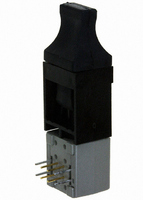
HFBR-14E4Z Avago Technologies US Inc., HFBR-14E4Z Datasheet - Page 13

HFBR-14E4Z
Manufacturer Part Number
HFBR-14E4Z
Description
XMITTER FIBER OPTIC HIGH PWR SC
Manufacturer
Avago Technologies US Inc.
Datasheet
1.HFBR-4401Z.pdf
(25 pages)
Specifications of HFBR-14E4Z
Wavelength
820nm
Voltage - Forward (vf) Typ
1.7V
Current - Dc Forward (if)
100mA
Voltage - Dc Reverse (vr) (max)
1.8V
Capacitance
55pF
Connector Type
SC
Data Rate Max
0.16Gbps
Supply Voltage
5V
Wavelength Typ
820nm
Leaded Process Compatible
Yes
Applications
100Base-SX Fast Ethernet, Media/Fiber Conversion, Switches, Routers, Hubs
Product
Transmitter
Data Rate
160 MBd
Diode Capacitance
55 pF
Maximum Rise Time
6.5 ns
Maximum Fall Time
6.5 ns
Maximum Output Current
25 mA
Operating Supply Voltage
4.75 V to 5.25 V
Maximum Operating Temperature
+ 85 C
Minimum Operating Temperature
- 40 C
Function
High performance fiber optic communication links for information systems and industrial applications.
Lead Free Status / RoHS Status
Lead free / RoHS Compliant
Spectral Bandwidth
-
Lead Free Status / Rohs Status
Details
For Use With
Multimode Glass, Hard Clad Silica
Lead Free Status / RoHS Status
Lead free / RoHS Compliant, Lead free / RoHS Compliant
Other names
516-2041
Available stocks
Company
Part Number
Manufacturer
Quantity
Price
Company:
Part Number:
HFBR-14E4Z
Manufacturer:
SHARP
Quantity:
21 040
Figure 8. System Propagation Delay Test Circuit and Waveform Timing Definitions.
Ethernet 20 MBd Link (HFBR-14x4Z/24x6Z)
(refer to Application Note 1038 for details)
Typical Link Performance
Notes:
1. Typical data at T
2. Typical performance of circuits shown in Figure 1 and Figure 3 of AN-1038 (see applications support section).
13
Parameter
Receiver Sensitivity
Link Jitter
Transmitter Jitter
Optical Power
LED Rise Time
LED Fall Time
Mean Difference
Bit Error Rate
Output Eye Opening
Data Format 50% Duty Factor
PULSE
GEN
½ 75451
A
= +25 °C, V
HFBR-2412Z RECEIVER
P
T
- FROM 1-METER
1N4150
I
10 W
F
TEST CABLE
10 W
CC
2, 6, 7
R
+15 V
S
= 5.0 V dc.
3
TRANSMITTER
Symbol
P
t
t
|t
BER
r
f
T
r
RESISTOR VALUE AS NEEDED FOR
SETTING OPTICAL POWER OUTPUT
FROM RECEIVER END OF TEST CABLE
- t
7 & 3
f
6
2
|
0.1 μF
R
L
560
+5 V
15 pF
Typ [1, 2]
-34.4
7.56
7.03
0.763
-15.2
1.30
3.08
1.77
10
36.7
20
INPUT (I
OUTPUT
-10
+
F
V
)
O
EQUIPMENT
ANALYSIS
eg. SCOPE
TIMING
V
Units
dBm average
ns pk-pk
ns pk-pk
ns pk-pk
dBm average
ns
ns
ns
ns
MBd
INPUT
I
P
F
O
T
1.5 V
50%
50%
5 V
MAX
0
t
PHL
100 ns
t
PHLT
Conditions
20 MBd D2D2 hexadecimal data
2 km 62.5/125 μm fiber
ECL Out Receiver
TTL Out Receiver
20 MBd D2D2 hexadecimal data
20 MBd D2D2 hexadecimal data-
Peak I
1 MHz square wave input
At AUI receiver output
MIN
t
PHL
PULSE REPETITION
FREQ = 1 MHz
F,ON
= 60 mA
MAX
100 ns
t
PHL
t
PHLT
MIN
t
PHL


