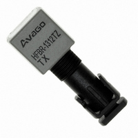
HFBR-1312TZ Avago Technologies US Inc., HFBR-1312TZ Datasheet - Page 2
HFBR-1312TZ
Manufacturer Part Number
HFBR-1312TZ
Description
XMITTER FIBER OPTIC ST 1300NM
Manufacturer
Avago Technologies US Inc.
Datasheet
1.HFBR-2316TZ.pdf
(7 pages)
Specifications of HFBR-1312TZ
Wavelength
1300nm
Spectral Bandwidth
185nm
Voltage - Forward (vf) Typ
1.4V
Voltage - Dc Reverse (vr) (max)
4V
Capacitance
16pF
Connector Type
ST
Function
Optical Transmitter for Industrial Applications
Product
Transmitter
Data Rate
20 MBd, 155 MBd
Diode Capacitance
16 pF
Maximum Rise Time
4 ns
Maximum Fall Time
4 ns
Operating Supply Voltage
6 VDC
Maximum Operating Temperature
+ 85 C
Minimum Operating Temperature
- 40 C
Package / Case
PDIP-8
Lead Free Status / RoHS Status
Lead free / RoHS Compliant
Current - Dc Forward (if)
-
Lead Free Status / Rohs Status
Lead free / RoHS Compliant
For Use With
Multimode Glass
Lead Free Status / RoHS Status
Lead free / RoHS Compliant, Lead free / RoHS Compliant
Other names
516-2032
Available stocks
Company
Part Number
Manufacturer
Quantity
Price
Company:

Part Number:
HFBR-1312TZ
Manufacturer:
Avago Technologies US Inc.
Quantity:
135


BOTTOM VIEW
CATHODE
HFBR-1312TZ Transmitter
Receiver
The HFBR-2316TZ receiver contains an InGaAs PIN photo-
diode and a low-noise transimpedance preamplifier that
operate in the 1300 nm wavelength region. The HFBR-
2316TZ receives an optical signal and converts it to an
analog voltage. The buffered output is an emitter-follower,
with frequency response from DC to typically 125 MHz.
Low-cost external components can be used to convert
the analog output to logic compatible signal levels for a
variety of data formats and data rates. The HFBR-2316TZ
is pin compatible with HFBR-24X6Z receivers and can be
used to extend the distance of an existing application by
substi-tuting the HFBR-2316TZ for the HFBR-2416Z.
Package Information
HFBR-0300Z Series transmitters and receivers are housed
is a dual-in-line package made of high strength, heat re-
sistant, chemically resistant, and UL V-0 flame retardant
2
ANODE
2, 6
* PIN 7 IS ELECTRICALLY ISOLATED FROM
PINS 1, 4, 5, AND 8, BUT IS CONNECTED
TO THE HEADER.
THE INTERNAL CIRCUITRY, BUT ARE
ELECTRICALLY CONNECTED TO EACH OTHER.
3
PINS 1, 4, 5, AND 8 ARE ISOLATED FROM
4
3
2
1
PIN
5
6
7
8
1
2
3
4
5
6
7*
8
PIN NO. 1
INDICATOR
FUNCTION
N.C.
ANODE
CATHODE
N.C.
N.C.
ANODE
N.C.
N.C.
BOTTOM VIEW
HFBR-2316TZ Receiver
* PINS 3 AND 7 ARE ELECTRICALLY
CONNECTED TO THE HEADER.
THE INTERNAL CIRCUITRY, BUT ARE
ELECTRICALLY CONNECTED TO EACH OTHER.
PINS 1, 4, 5, AND 8 ARE ISOLATED FROM
4
3
2
1
5
6
7
8
PIN
PIN NO. 1
INDICATOR
1
4
5
8
3*
7*
2
6
FUNCTION
N.C.
SIGNAL
V
N.C.
N.C.
V
V
N.C.
EE
CC
EE
plastic. Transmitters are identified by the brown port color;
receivers have black ports. The package is auto-insert-
able and wave solderable for high volume production
applications.
Note: The “T” in the product numbers indicates a Threaded
ST connector (panel mountable), for both transmitter and
receiver.
Handling and Design Information
When soldering, it is advisable to leave the protective
cap on the unit to keep the optics clean. Good system
performance requires clean port optics and cable ferrules
to avoid obstructing the optical path. Clean compressed
air is often sufficient to remove particles of dirt; methanol
on a cotton swab also works well.
6
2
3, 7
V
ANALOG
SIGNAL
V
CC
EE
HFBR-0300Z Series
Mechanical Dimensions
(0.020 X 0.015)
PINS 2,3,6,7
(0.495)
PINS 1,4,5,8
(0.018)
PART NUMBER
DATE CODE
0.51 X 0.38
12.6
0.46
(0.140)
(0.150)
(0.300)
3.81
7.62
3.60
DIA
(0.100)
2.54
(0.495)
12.6
(1.174)
(0.050)
PIN NO. 1
INDICATOR
(0.100)
29.8
1.27
2.54
(0.248)
(0.202)
6.30
(0.327)
5.10
8.31
(0.400)
10.20
(0.199)
3/8-32 UNEF-2A
5.05
(0.278)
7.05
DIA.
Related parts for HFBR-1312TZ
Image
Part Number
Description
Manufacturer
Datasheet
Request
R

Part Number:
Description:
XMITTER FIBER OPTIC 600NM 10MBD
Manufacturer:
Avago Technologies US Inc.
Datasheet:

Part Number:
Description:
XMITTER OPT HI PERFORMANCE HORZ
Manufacturer:
Avago Technologies US Inc.
Datasheet:

Part Number:
Description:
XMITTER FIBER OPTIC SMA SERCOS
Manufacturer:
Avago Technologies US Inc.
Datasheet:

Part Number:
Description:
XMITTER FIBER OPTIC PROFIBUS ST
Manufacturer:
Avago Technologies US Inc.
Datasheet:

Part Number:
Description:
XMITTER FIBER OPTIC SERCOS SMA
Manufacturer:
Avago Technologies US Inc.
Datasheet:
Part Number:
Description:
XMITTER FIBER OPTIC INTERBUS SMA
Manufacturer:
Avago Technologies US Inc.
Datasheet:
Part Number:
Description:
XMITTER FIBER OPTIC PROFIBUS ST
Manufacturer:
Avago Technologies US Inc.
Datasheet:

Part Number:
Description:
FIBER OPTIC CBL SIMPLEX 1=100M
Manufacturer:
Avago Technologies US Inc.
Datasheet:

Part Number:
Description:
FIBER OPTIC CBL SIMPLEX 1=500M
Manufacturer:
Avago Technologies US Inc.
Datasheet:

Part Number:
Description:
FIBER OPTIC CONN LATCH GRY SIMPL
Manufacturer:
Avago Technologies US Inc.
Datasheet:

Part Number:
Description:
FIBER OPTIC CONN LATCH BLU SIMPL
Manufacturer:
Avago Technologies US Inc.
Datasheet:
Part Number:
Description:
XMITTER VERSATILE LINK HORZ
Manufacturer:
Avago Technologies US Inc.
Datasheet:

Part Number:
Description:
Fiber Optic Transmitters, Receivers, Transceivers 1300nm 155MBd 16-pin DIP ST Rx
Manufacturer:
Avago Technologies US Inc.

Part Number:
Description:
FIBER OPTIC CBL DUPLEX 1=100M
Manufacturer:
Avago Technologies US Inc.
Datasheet:
Part Number:
Description:
FIBER OPTIC CBL SIMPLEX 1=500M
Manufacturer:
Avago Technologies US Inc.
Datasheet: