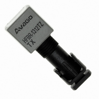
HFBR-1312TZ Avago Technologies US Inc., HFBR-1312TZ Datasheet - Page 6

HFBR-1312TZ
Manufacturer Part Number
HFBR-1312TZ
Description
XMITTER FIBER OPTIC ST 1300NM
Manufacturer
Avago Technologies US Inc.
Datasheet
1.HFBR-2316TZ.pdf
(7 pages)
Specifications of HFBR-1312TZ
Wavelength
1300nm
Spectral Bandwidth
185nm
Voltage - Forward (vf) Typ
1.4V
Voltage - Dc Reverse (vr) (max)
4V
Capacitance
16pF
Connector Type
ST
Function
Optical Transmitter for Industrial Applications
Product
Transmitter
Data Rate
20 MBd, 155 MBd
Diode Capacitance
16 pF
Maximum Rise Time
4 ns
Maximum Fall Time
4 ns
Operating Supply Voltage
6 VDC
Maximum Operating Temperature
+ 85 C
Minimum Operating Temperature
- 40 C
Package / Case
PDIP-8
Lead Free Status / RoHS Status
Lead free / RoHS Compliant
Current - Dc Forward (if)
-
Lead Free Status / Rohs Status
Lead free / RoHS Compliant
For Use With
Multimode Glass
Lead Free Status / RoHS Status
Lead free / RoHS Compliant, Lead free / RoHS Compliant
Other names
516-2032
Available stocks
Company
Part Number
Manufacturer
Quantity
Price
Company:
Part Number:
HFBR-1312TZ
Manufacturer:
Avago Technologies US Inc.
Quantity:
135
HFBR-2316TZ Receiver Absolute Maximum Ratings
HFBR-2316TZ Receiver Electrical/Optical and Dynamic Characteristics
0 to 70°C; 4.75 V < V
6
CAUTION: The small junction sizes inherent to the design of this bipolar component increase the component’s susceptibility to dam-
age from electrostatic discharge (ESD). It is advised that normal static precautions be taken in handling and assembly of this com-
ponent to prevent damage and/or degradation which may be induced by ESD.
Noise Input Power (RMS)
Parameter
Responsitivity
RMS Output Noise
Voltage
Equivalent Optical
Peak Input Optical Power
Output Resistance
DC Output Voltage
Supply Current
Electrical Bandwidth
Bandwidth * Rise
Time Product
Electrical Rise, Fall
Times, 10-90%
Pulse-Width
Distortion
Overshoot
Storage Temperature
Operating Temperature
Lead Soldering Temperature
Signal Pin Voltage
Supply Voltage
Output Current
Cycle Time
Parameter
CC
- V
EE
< 5.25 V; power supply must be filtered (see note 2).
R
P
R
Symbol
62.5 µm
P
P
PWD
V
BW
V
9 µm
N, RMS
t
P
R
I
O,DC
r
CC
NO
,t
O
R
f
E
Min.
6.5
8.5
0.8
75
Symbol
V
CC
V
T
T
I
- V
O
A
O
S
0.032
Typ.
0.41
EE
125
-45
0.4
1.8
3.3
0.4
13
17
30
9
2
[3]
0.071
-41.5
-11.0
Max.
0.59
1.0
2.6
5.3
1.0
19
80
15
Min.
-0.5
-0.5
-55
-40
mV/µW
mV
mV
Ohm
Hz *s
dBm
dBm
MHz
Unit
µW
µW
mA
ns
ns
%
V
RMS
RMS
Max.
+85
260
V
6.0
85
10
25
λ
Multimode Fiber
62.5/125 µm
Singlemode Fiber
9/125 µm
100 MHz Bandwidth,
P
Unfiltered Bandwidth
P
@ 100 MHz, P
50 MHz, 1 ns PWD
f = 50 MHz
V
P
R
-3 dB electrical
P
@ 50 MHz
P
P
CC
p
R
R
CC
R
LOAD
R
R
R
= 0 µW
= 0 µW
= 0 µW
= -15 dBm peak,
= -11 dBm, peak
= -15 dBm, peak
= 1300 nm, 50 MHz
= 5 V, V
= ∞
Condition
EE
Unit
mA
= 0 V
°C
°C
°C
V
V
s
R
= 0 µW
Reference
Note 1
Note 2
Note 4
Fig. 6, 10
Note 5
Fig. 7
Note 5
Note 6
Fig. 8
Note 7
Note 11
Note 8
Fig. 9
Note 6,9
Fig. 8
Note 10
Ref.


