HLMP-NL06 Avago Technologies US Inc., HLMP-NL06 Datasheet - Page 12
HLMP-NL06
Manufacturer Part Number
HLMP-NL06
Description
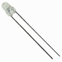
LED 3MM ALINGAP 590NM AMB 60DEG
Manufacturer
Avago Technologies US Inc.
Specifications of HLMP-NL06
Viewing Angle
60°
Package / Case
Radial - 2 Lead
Color
Amber
Millicandela Rating
96.2mcd
Current - Test
20mA
Wavelength - Dominant
590nm
Wavelength - Peak
592nm
Voltage - Forward (vf) Typ
2.02V
Lens Type
Clear, Amber Tinted
Lens Style/size
Round, 3mm, T-1
Height
5.70mm
Mounting Type
Through Hole
Resistance Tolerance
590nm
Led Size
T-1
Illumination Color
Amber
Lens Color/style
Non-Diffused
Operating Voltage
1.9 V
Wavelength
600 nm
Luminous Intensity
90.2 mcd
Mounting Style
Through Hole
Color, Emitted
Amber
Color, Lens
Clear
Package Type
3 mm (T-1)
Lead Free Status / RoHS Status
Lead free / RoHS Compliant
Luminous Flux @ Current - Test
-
Lead Free Status / Rohs Status
Lead free / RoHS Compliant
Other names
516-1769
HLMP-NL06
HLMP-NL06
Available stocks
Company
Part Number
Manufacturer
Quantity
Price
Company:

Part Number:
HLMP-NL06
Manufacturer:
AVAGO
Quantity:
40 000
Company:
Part Number:
HLMP-NL06
Manufacturer:
AVAGO
Quantity:
50 000
Company:
Part Number:
HLMP-NL06#002
Manufacturer:
AVAGO
Quantity:
40 000


Precautions
Lead Forming
• The leads of an LED lamp may be preformed or cut to
• If lead forming is required before soldering, care must
• It is recommended that tooling made to precisely
Soldering Conditions
• Care must be taken during PCB assembly and soldering
• The closest LED is allowed to solder on board is 1.59
• Recommended soldering conditions:
For product information and a complete list of distributors, please go to our website:
Avago, Avago Technologies, and the A logo are trademarks of Avago Technologies Limited in the United States and other countries.
Data subject to change. Copyright © 2008 Avago Technologies Limited. All rights reserved. Obsoletes 5989-4257EN
AV02-1014EN - January 23, 2008
Wave Soldering
Pre-heat Temperature 105 °C Max.
Pre-heat Time
Peak Temperature
Dwell Time
Figure 7. Recommended wave soldering profile.
length prior to insertion and soldering into PC board.
be taken to avoid any excessive mechanical stress
induced to LED package. Otherwise, cut the leads
of LED to length after soldering process at room
temperature. The solder joint formed will absorb the
mechanical stress of the lead cutting from traveling to
the LED chip die attach and wirebond.
form and cut the leads to length rather than rely upon
hand operation.
process to prevent damage to LED component.
mm below the body (encapsulant epoxy) for those
parts without standoff.
250
200
150
100
50
30
0
10
FLUXING
TURBULENT WAVE
PREHEAT
20
30
TIME – SECONDS
Dipping
30 sec Max.
250 °C Max.
3 sec Max.
40
50
60
70
LAMINAR WAVE
HOT AIR KNIFE
80
Manual Solder
–
–
260 °C Max.
5 sec Max.
90
100
CONVEYOR SPEED = 1.83 M/MIN (6 FT/MIN)
PREHEAT SETTING = 150°C (100°C PCB)
SOLDER WAVE TEMPERATURE = 245°C
AIR KNIFE AIR TEMPERATURE = 390°C
AIR KNIFE DISTANCE = 1.91 mm (0.25 IN.)
AIR KNIFE ANGLE = 40°
SOLDER: SN63; FLUX: RMA
NOTE: ALLOW FOR BOARDS TO BE
SUFFICIENTLY COOLED BEFORE EXERTING
MECHANICAL FORCE.
www.avagotech.com
BOTTOM SIDE
OF PC BOARD
TOP SIDE OF
PC BOARD
• Wave soldering parameter must be set and maintained
• If necessary, use fixture to hold the LED component
• Proper handling is imperative to avoid excessive
• Special attention must be given to board fabrication,
• Recommended PC board plated through hole sizes
Note: Refer to application note AN1027 for more information on
soldering LED components.
LED Component
Lead Size
0.457 x 0.457 mm
(0.018 x 0.018 inch)
0.508 x 0.508 mm
(0.020 x 0.020 inch)
according to recommended temperature and dwell
time in the solder wave. Customer is advised to
periodically check on the soldering profile to ensure
the soldering profile used is always conforming to
recommended soldering condition.
in proper orientation with respect to the PCB during
soldering process.
thermal stresses to LED components when heated.
Therefore, the soldered PCB must be allowed to cool
to room temperature, 25°C, before handling.
solder masking, surface plating and lead holes size
and component orientation to assure solderability.
for LED component leads:
Diagonal
0.646 mm
(0.025 inch)
0.718 mm
(0.028 inch)
Plated Through
Hole Diameter
0.976 to 1.078 mm
(0.038 to 0.042 inch)
1.049 to 1.150 mm
(0.041 to 0.045 inch)
Related parts for HLMP-NL06
Image
Part Number
Description
Manufacturer
Datasheet
Request
R

Part Number:
Description:
LED 3MM 569NM GREEN DIFF
Manufacturer:
Avago Technologies US Inc.
Datasheet:

Part Number:
Description:
LED 5MM 635NM HE RED WATER CLEAR
Manufacturer:
Avago Technologies US Inc.
Datasheet:

Part Number:
Description:
LED 5MM 639NM RED WATER CLEAR
Manufacturer:
Avago Technologies US Inc.
Datasheet:

Part Number:
Description:
LED LT BAR 8.89X3.81MM SGL GREEN
Manufacturer:
Avago Technologies US Inc.
Datasheet:

Part Number:
Description:
LED LT BAR 19.05X3.81MM SGL YLW
Manufacturer:
Avago Technologies US Inc.
Datasheet:

Part Number:
Description:
LED Lamp
Manufacturer:
Avago Technologies US Inc.
Datasheet:

Part Number:
Description:
LED 5MM FLAT TOP INGAN WHITE
Manufacturer:
Avago Technologies US Inc.
Datasheet:
Part Number:
Description:
LED 5MM FLAT TOP INGAN WHITE
Manufacturer:
Avago Technologies US Inc.
Datasheet:
Part Number:
Description:
LED 5MM FLAT TOP INGAN WHITE
Manufacturer:
Avago Technologies US Inc.
Datasheet:
Part Number:
Description:
LED 5MM FLAT TOP INGAN WHITE
Manufacturer:
Avago Technologies US Inc.
Datasheet:

Part Number:
Description:
LED DOME 5V 635NM HER DFF RA AXL
Manufacturer:
Avago Technologies US Inc.
Datasheet:

Part Number:
Description:
LED DOME 5V 565NM GN DIFF RA AXL
Manufacturer:
Avago Technologies US Inc.
Datasheet:

Part Number:
Description:
LED DOME 583NM YLW DIFF RA AXIAL
Manufacturer:
Avago Technologies US Inc.
Datasheet:

Part Number:
Description:
LED 5MM GAP GRN RA HOUSING TH
Manufacturer:
Avago Technologies US Inc.
Datasheet:

Part Number:
Description:
LED 3MM GAP DIFF RED RA HOUSING
Manufacturer:
Avago Technologies US Inc.
Datasheet: