HSMF-A201-A00J1 Avago Technologies US Inc., HSMF-A201-A00J1 Datasheet - Page 5
HSMF-A201-A00J1
Manufacturer Part Number
HSMF-A201-A00J1
Description
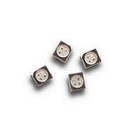
LED IND RED/GRN TOP MOUNT 4PLCC
Manufacturer
Avago Technologies US Inc.
Type
Bi-Colorr
Datasheet
1.HSMF-A201-A00J1.pdf
(16 pages)
Specifications of HSMF-A201-A00J1
Package / Case
4-PLCC
Viewing Angle
120°
Color
Green-Yellow, Red
Millicandela Rating
20mcd Green-Yellow, 16mcd Red
Current - Test
20mA
Wavelength - Dominant
569nm, 626nm
Wavelength - Peak
565nm, 635nm
Voltage - Forward (vf) Typ
2.2V Green-Yellow, 2.2V Red
Lens Type
Clear
Lens Style/size
Round, 2.2mm
Size / Dimension
3.20mm L x 2.80mm W
Height
1.90mm
Mounting Type
Surface Mount
Resistance Tolerance
569nm, 626nm
Led Size
3.2 mm x 2.8 mm
Illumination Color
Red, Yellow-Green
Lens Color/style
Diffused
Operating Voltage
1.9 V, 2.2 V
Wavelength
626 nm, 569 nm
Luminous Intensity
16 mcd, 20 mcd
Mounting Style
SMD/SMT
Operating Current
20 mA
Lens Shape
Flat Round
Maximum Operating Temperature
+ 100 C
Minimum Operating Temperature
- 55 C
Peak Wavelength
635 nm, 565 nm
Package Type
PLCC
Emitting Color
Red/Yellow Green
Test Current (it)
20mA
Forward Current
30/20mA
Dominant Wave Length
626/569nm
Forward Voltage
2.6V
Product Length (mm)
2.8mm
Product Height (mm)
1.8mm
Product Depth (mm)
3.2mm
Mounting
Surface Mount
Shape Type
Circular
Chip Material
GaP
Main Category
Chip LED
Number Of Elements
2
Pin Count
4
Operating Temperature Classification
Industrial
Operating Temp Range
-55C to 100C
Reverse Voltage
5V
Power Dissipation
78/48mW
Lens Dimensions
2.2x2.2x0.8mm
Lead Free Status / RoHS Status
Lead free / RoHS Compliant
Luminous Flux @ Current - Test
-
Lead Free Status / Rohs Status
Lead free / RoHS Compliant
Available stocks
Company
Part Number
Manufacturer
Quantity
Price
Company:

Part Number:
HSMF-A201-A00J1
Manufacturer:
AVAGO
Quantity:
40 000
Company:
Part Number:
HSMF-A201-A00J1
Manufacturer:
AVAGO
Quantity:
50 000
Part Number:
HSMF-A201-A00J1
Manufacturer:
BROADCOM
Quantity:
20 000


Optical Characteristics (T
N
1. The dominant wavelength, λ
2. θ
3. Radiant intensity, I
Electrical Characteristics (T
5
AlInGaP Red
AlInGaP Yellow Green
GaP Red
AlGaAs Red
AlInGaP Red Orange
GaP Orange
AlInGaP Amber
GaP Yellow
AlInGaP Amber
GaP Yellow Green
GaP Emerald Green
InGaN Green
InGaN Blue
GaN Blue
GaP
AS AlGaAs
AlInGaP
GaN Blue
InGaN
Color
Dice Technology
otes:
the luminous efficacy in lumens/watt.
1/2
is the off-axis angle where the luminous intensity is 1/2 the peak intensity.
e
in watts/steradian, may be calculated from the equation I
A
D
= 25°C)
Forward Voltage
V
Typ.
2.2
1.9
1.9
3.9
3.4
, is derived from the CIE Chromaticity Diagram and represents the color of the device.
A
F
= 25°C)
(Volts) @ I
Peak
Wavelength
λ
Typ.
635
645
635
621
600
592
583
592
565
558
523
468
428
575
PEAK
(nm)
F
Max.
2.6
2.6
2.4
4.3
4.05
= 20mA
Dominant
Wavelength
λ
Typ.
626
637
626
615
602
590
585
590
569
560
525
470
462
571
D
(nm)
[1]
Reverse Voltage
V
Min.
5
5
5
-
-
R
@ 100 µA
Viewing Angle
2θ
Typ.
120
120
120
120
120
120
120
120
120
120
120
120
120
120
1/2
e
= I
(Degrees)
v
/η
v
, where I
[2]
v
is the luminous intensity in candelas and η
Luminous
Efficacy η
(lm/W)
Typ.
120
63
150
240
380
480
580
480
590
650
500
75
65
620
Reverse Voltage
V
Min.
-
-
-
5
5
R
[3]
@ 10 µA
v
Luminous Intensity/
Total Flux
I
Typ.
0.45
0.45
0.45
0.45
0.45
0.45
0.45
0.45
0.45
0.45
0.45
0.45
0.45
0.45
v
(mcd) /Φ
v
(mlm)
v
is
Related parts for HSMF-A201-A00J1
Image
Part Number
Description
Manufacturer
Datasheet
Request
R

Part Number:
Description:
OPTOCOUPLER GATE DRV 2A 16-SOIC
Manufacturer:
Avago Technologies US Inc.
Datasheet:
Part Number:
Description:
OPTOCOUPLER 2CH 2.5A 16-SOIC
Manufacturer:
Avago Technologies US Inc.
Datasheet:

Part Number:
Description:
OPTOCOUPLER GATE DRV 0.4A 16SOIC
Manufacturer:
Avago Technologies US Inc.
Datasheet:

Part Number:
Description:
OPTOCOUPLER 2.0A 250KHZ 8-DIP
Manufacturer:
Avago Technologies US Inc.
Datasheet:

Part Number:
Description:
OPTOCOUPLER 2.0A 250KHZ GW 8-SMD
Manufacturer:
Avago Technologies US Inc.
Datasheet:

Part Number:
Description:
OPTOCOUPLER 2CH 15MBD 3.3V 8SOIC
Manufacturer:
Avago Technologies US Inc.
Datasheet:
Part Number:
Description:
OPTOCOUPLER DARL-OUT 8-DIP
Manufacturer:
Avago Technologies US Inc.
Datasheet:
Part Number:
Description:
OPTOCOUPLER IGBT DRIVE 0.4A 8DIP
Manufacturer:
Avago Technologies US Inc.
Datasheet:
Part Number:
Description:
OPTOCOUPLER DARL-OUT 8-DIP
Manufacturer:
Avago Technologies US Inc.
Datasheet:

Part Number:
Description:
OPTOCOUPLER 1CH 1MBS 8-SMD GW
Manufacturer:
Avago Technologies US Inc.
Datasheet:
Part Number:
Description:
OPTOCOUPLER GATE DRIVER 8-DIP
Manufacturer:
Avago Technologies US Inc.
Datasheet:

Part Number:
Description:
OPTOCOUPLER GATE DRIVER 8-SMD
Manufacturer:
Avago Technologies US Inc.
Datasheet:

Part Number:
Description:
OPTOCOUPLER PHOTOTRANS 4-SMD
Manufacturer:
Avago Technologies US Inc.
Datasheet:

Part Number:
Description:
OPTOCOUPLER W/BASE 6-DIP
Manufacturer:
Avago Technologies US Inc.
Datasheet:

Part Number:
Description:
ISOLAT 5KVRMS 4CH TRANS 16SMD GW
Manufacturer:
Avago Technologies US Inc.
Datasheet: