HLMA-KL00-I0000 Avago Technologies US Inc., HLMA-KL00-I0000 Datasheet - Page 2
HLMA-KL00-I0000
Manufacturer Part Number
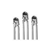
HLMA-KL00-I0000
Description
LED 3MM ALINGAP HI PERF AMBER
Manufacturer
Avago Technologies US Inc.
Specifications of HLMA-KL00-I0000
Viewing Angle
45°
Package / Case
Radial - 2 Lead
Color
Amber
Millicandela Rating
200mcd
Current - Test
20mA
Wavelength - Dominant
590nm
Wavelength - Peak
592nm
Voltage - Forward (vf) Typ
1.9V
Lens Type
Clear
Lens Style/size
Round, 3mm, T-1
Height
4.70mm
Mounting Type
Through Hole
Resistance Tolerance
590nm
Led Size
T-1
Illumination Color
Amber
Lens Color/style
Untinted Non-Diffused
Operating Voltage
1.9 V
Wavelength
590 nm
Luminous Intensity
200 mcd
Operating Current
20 mA
Lens Dimensions
3 mm
Lens Shape
Dome
Maximum Operating Temperature
+ 100 C
Minimum Operating Temperature
- 40 C
Mounting Style
Through Hole
Lead Free Status / RoHS Status
Lead free / RoHS Compliant
Luminous Flux @ Current - Test
-
Lead Free Status / Rohs Status
Lead free / RoHS Compliant
Available stocks
Company
Part Number
Manufacturer
Quantity
Price
Company:

Part Number:
HLMA-KL00-I0000
Manufacturer:
AVAGO
Quantity:
40 000
Company:
Part Number:
HLMA-KL00-I0000
Manufacturer:
AVAGO
Quantity:
50 000


Device Selection Guide
Tolerance for each intensity bin limit is ± 15%.
Absolute Maximum Ratings at T
Notes:
1. Derate linearly as shown in Figure 4.
. Any pulsed operation cannot exceed the Absolute Max Peak Forward Current or the Max Allowable Time Average Power as specified in Figure 5.
3. The transient peak current is the maximum nonrecurring peak current the device can withstand without damaging the LED die and wire bonds.
4. Drive Currents between 10 mA and 30 mA are recommended for best long term performance.
5. Operation at currents below 10 mA is not recommended, please contact your Avago Technologies sales representative.
Optical Characteristics at T
Notes:
1. The luminous intensity, Iv, is measured at the mechanical axis of the lamp package. The actual peak of the spatial radiation pattern may not be
. The dominant wavelength, ld, is derived from the CIE Chromaticity Diagram and represents the color of the device.
3. q1/ is the off-axis angle where the luminous intensity is 1/ the peak intensity.
Electrical Characteristics at T
Part Number
HLMA-KL00-I0000
HLMA-KH00-J0000
Parameter
DC Forward Current
Peak Forward Current
Time Average Input Power
Transient Forward Current
Reverse Voltage (I
Operating Temperature Range
Storage Temperature
Junction Temperature
Part
Number
HLMA-
KL00
KH00
PART NuMBERHLMA-
KL00
KH00
aligned with this axis.
R
= 100 mA)
[1,4,5]
I
V
Min,
[]
(mcd) @ 20 mA
Forward Voltage
Typ.
35
35
1.9
1.9
@ I
Luminous
Intensity
V
[3]
[]
F
Color
Amber
Red Orange
F
(Volts)
= 20 mA
A
(10 ms Pulse)
= 25°C
A
= 25°C
Typ.
00
00
Max.
A
.4
.4
= 25°C
[1]
Wavelength
Reverse Breakdown
Min.
l
Peak
Dominant Wavelength
Typ.
59
61
5
5
peak
(nm)
@ I
V
R
R
= 100
ld (nm) Typ
(Volts)
590nm
615nm
m
Typ.
A
5
5
584.5
611.0
Min.
Color, Dominant
Wavelength
l
d
[2]
(nm)
Value
50
00
103
500
5
-40 to 100
-40 to 100
110
597.0
63.0
Max.
Capacitance
C (pF) V
f = 1 MHz
Iv (mcd) at 20 mA-Min
Typ.
40
40
Luminous Intensity
F
= 0,
2q
4.3
39.6
½
Viewing
Angle
Degrees
Unit
mA
mA
mW
mA
V
°C
°C
°C
Typ.
45
45
Resistance
Thermal
R
[3]
q
J-PIN
(°C/W)
90
90
Luminous
h
Efficacy
(lm/w)
v
480
63
Iv (mcd) at 20 mA-Max
Luminous Intensity
Speed of Response
Time Constant
-
-
e
Typ.
13
13
-t/ts
Flux (mlm)
Luminous
@20 mA
Typ.
500
500
t
s
(ns)
Related parts for HLMA-KL00-I0000
Image
Part Number
Description
Manufacturer
Datasheet
Request
R


Part Number:
Description:
OPTOCOUPLER GATE DRV 2A 16-SOIC
Manufacturer:
Avago Technologies US Inc.
Datasheet:
Part Number:
Description:
OPTOCOUPLER 2CH 2.5A 16-SOIC
Manufacturer:
Avago Technologies US Inc.
Datasheet:

Part Number:
Description:
OPTOCOUPLER GATE DRV 0.4A 16SOIC
Manufacturer:
Avago Technologies US Inc.
Datasheet:

Part Number:
Description:
OPTOCOUPLER 2.0A 250KHZ 8-DIP
Manufacturer:
Avago Technologies US Inc.
Datasheet:

Part Number:
Description:
OPTOCOUPLER 2.0A 250KHZ GW 8-SMD
Manufacturer:
Avago Technologies US Inc.
Datasheet:

Part Number:
Description:
OPTOCOUPLER 2CH 15MBD 3.3V 8SOIC
Manufacturer:
Avago Technologies US Inc.
Datasheet:
Part Number:
Description:
OPTOCOUPLER DARL-OUT 8-DIP
Manufacturer:
Avago Technologies US Inc.
Datasheet:
Part Number:
Description:
OPTOCOUPLER IGBT DRIVE 0.4A 8DIP
Manufacturer:
Avago Technologies US Inc.
Datasheet:
Part Number:
Description:
OPTOCOUPLER DARL-OUT 8-DIP
Manufacturer:
Avago Technologies US Inc.
Datasheet:

Part Number:
Description:
OPTOCOUPLER 1CH 1MBS 8-SMD GW
Manufacturer:
Avago Technologies US Inc.
Datasheet:
Part Number:
Description:
OPTOCOUPLER GATE DRIVER 8-DIP
Manufacturer:
Avago Technologies US Inc.
Datasheet:

Part Number:
Description:
OPTOCOUPLER GATE DRIVER 8-SMD
Manufacturer:
Avago Technologies US Inc.
Datasheet:

Part Number:
Description:
OPTOCOUPLER PHOTOTRANS 4-SMD
Manufacturer:
Avago Technologies US Inc.
Datasheet:

Part Number:
Description:
OPTOCOUPLER W/BASE 6-DIP
Manufacturer:
Avago Technologies US Inc.
Datasheet: