AC/DC converter
AC220V input, output
Input voltage
Output voltage1
Output current1
Output voltage2
Output current2
Line regulation1
Line regulation2
Load regulation1
Load regulation2
Output ripple voltage1
Output ripple voltage2
Power conversion efficiency1
Power conversion efficiency2
1 Maximum output current varies depending on ambient temperature ; please refer to derating curve.
2 Please refer to Load regulation, Conversion effciency.
1 Maximum input voltage at steady mode is 358V, but the over-applied voltage is 400Vpk, within 10 seconds.
2 Maximum output current is the peak of load current after the output smoothing capacitor. The maximum heating part of this module
C220V input, output 1 : 15V/80mA, output
Input voltage
Maximum output current
Maximum output current
ESD endurance
Operating temperature range
Storage temperature range
External components setting
Absolute Maximum Ratings
Electrical Characteristics
Application circuit
have to be below 150 C including self-heating and ambient temperature. And the average current must be in the range of electrical
characteristics below.
FUSE: Fuse
C1: Capacitor for input
C2: For noise terminal
C3: Capacitor for Output
C4: Capacitor for Output
L1: Choke coil
D1: Rectifier diode
R1: Rush current limiting
R2: For noise terminal
ZNR: Varistor
Parameter
Be sure to use fuse for safety.
Vi
BP5085-15
For acutual usage, Please kindly evaluate and confirm our part mounted in your product,
Especially, Please make sure to confirm whether the load current exceed Max. rated current
by using the current probe.
voltage smoothing
voltage reduction
resistance
(15V output)
(5V output)
Ii
Parameter
D1
ZNR
R1
DC motor
Symbol
V15
Vp1
Vp2
C1
Vr1
Vr2
I15
Vl1
Vl2
V5
Vi
I5
R2
1
2
(15V)
(5V)
1
FUSE
C2
Please make sure to use quick acting fuse 1A / Please use the fuse resistance for R2.
Capacitance : 33 F 820 F Rated voltage : 450V or higher
Ripple current is 0.13Arms above.
Capacitance : 0.1 F 0.22 F Rated voltage : 450V or higher
Film capacitor or ceramic capacitor. Reduce the noise terminal voltage.
The constant value should be evaluated in the set.
Capacitance : 220 F 1000 F Rated voltage : 35V or higher,
ESR is 0.16 max. Ripple current is 0.4Arms above.
Output ripple voltage is influenced. Please evaluate it in the actual se
Capacitance : 220 F 1000 F Rated voltage : 16V or higher,
ESR is 0.25 max. Ripple current is 0.4Arms above.
Output ripple voltage is influenced. Please evaluate it in the actual set.
L : 1mH Allowable current : 600mA or higher.
Please use the one that is hard to be magnetic saturated even in the high temperature.
In the absolute maximum ratings, the reverse peak voltage should be
800V or higher, the average rectifying current should be 1A or higher,and
the peak surge current should be 40A or higher.
For rush current, to use the large capacity diode for surge current is recommended.
Limiting resistance must be used because rush current at powering up is
applied in proportion to the C1 capacitance.Please determine the resistance value after confirming
the rising characteristics of the module at powering up.
10
The constant value should be evaluated in set.
Varistor must be used. It protects this part from lightning surge andstatic electricity.
14.0
4.75
Min.
226
60
45
0.3
0.3
0.3
0.3
4 6 8 10 12 14 16
0
0
Symbol
I15o
22 1/4W Reduce the noise terminal voltage.Please set it,if necessary.
Vsurge
I5o
15V/80mA, output 2 : 5V/350mA
L1
Topr
Tstg
Vi
C3
MAX
MAX
15.0
0.05
0.05
Typ.
282
5.0
0.1
0.1
0.1
0.1
70
55
Max.
16.0
5.25
358
350
0.3
0.3
0.3
0.3
0.2
0.2
80
C4
Io
25
20
Limits
Vo
Vp-p
Vp-p
400
350
Unit
mA
mA
80
%
%
2
V
V
V
V
V
V
V
Pin No.
105
10
11
12
13
14
15
16
80
1
2
3
4
5
6
7
8
9
DC
Vi=282V, I15=80mA, I5=0mA
Vi=282V
Vi=282V, I15=0mA, I5=200mA
Vi=282V
Vi=226~358V, I15=80mA, I5=0mA
Vi=226~358V, I15=0mA, I5=350mA
Vi=282V, I15=0~80mA, I5=0mA
Vi=282V, I15=0mA, I5=0 350mA
Vi=282V, I15=80mA, I5=0mA
Vi=282V, I15=0mA, I5=350mA
Vi=282V, I15=80mA, I5=0mA
Vi=282V, I15=0mA, I5=350mA
Input terminal Vi(282VDC)
Not used
Not used
COMMON1
Not used
Choke coil connect
Not used
Choke coil connect
Not used
15V output terminal
Not used
15V input terminal
Not used
COMMON2
Not used
Output terminal Vo(5V)
5V/350mA
Function
1
2
2
Conditions
mApk
mApk
Unit
kV
V
C
C
3
3
4
4
4
4
16.0
15.8
15.6
15.4
15.2
15.0
14.8
14.6
14.4
14.2
14.0
100
5.8MAX
100
Dimension(Unit :
Derating Curve
Conversion Efficeincy
Load Regulation
Surface Temperature Rising
20
18
16
14
12
10
90
80
70
60
50
40
30
20
10
Conversion Efficiency
90
80
70
60
50
40
30
20
10
Surface Temperature Rising
0
8
6
4
2
0
-30
0
Ambient Temperature Ta( C)
0
0
0
Load Regulation
Derating Curve
(15V output) (I5=0mA, Vi=141V)
Output Current I15(mA)
-20 -10
Output Current I15(mA)
Output Current I15(mA)
Operation Range
(I5=0mA, Vi=282V)
20
20
20
0 10
(I5=0mA, Vi=282V)
1
7.62
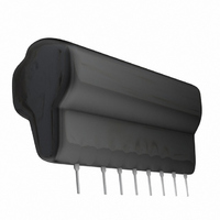
BP5085-15
20
40
30
40
40
4
40
2.54 15=38.1
(15V output)
50
(15V output)
48.5MAX.
6
(15V output)
0.5 0.1
60
60
1.3 0.2
60
60
70
8
80
10 12 14 16
80
80
80
90
5.08
400
350
300
250
200
150
100
100
5.3
5.2
5.1
5.0
4.9
4.8
4.7
20
18
16
14
12
10
50
90
80
70
60
50
40
30
20
10
Surface Temperature Rising
0
Conversion Efficiency
8
6
4
2
0
-30
0
Ambient Temperature Ta( C)
0
0
0
mm
Load Regulation
(5V output) (I15=0mA, Vi=141V)
Derating Curve
-20 -10
Output Current I5(mA)
Output Current I5(mA)
Output Current I5(mA)
50
50
50
Operation Range
(I15=0mA, Vi=282V)
(I15=0mA, Vi=282V)
0 10
100
100
100
)
14.0MAX.
150
150
20
150
9.0MAX.
30
5.0MAX.
200
200
200
0.25 0.05
40
(5V output)
50
250
250 300
(5V output)
250
(5V output)
60
1/2
70
300
300
80
350
350
350
90