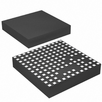
LTM4612IV#PBF Linear Technology, LTM4612IV#PBF Datasheet - Page 16

LTM4612IV#PBF
Manufacturer Part Number
LTM4612IV#PBF
Description
IC BUCK SYNC ADJ 5A 133LGA
Manufacturer
Linear Technology
Series
µModuler
Type
Point of Load (POL) Non-Isolatedr
Datasheet
1.LTM4612EVPBF.pdf
(26 pages)
Specifications of LTM4612IV#PBF
Design Resources
LTM4612 Spice Model
Output
3.3 ~ 15 V
Number Of Outputs
1
Power (watts)
75W
Mounting Type
Surface Mount
Voltage - Input
5 ~ 36 V
Package / Case
133-LGA
1st Output
3.3 ~ 15 VDC @ 5A
Size / Dimension
0.59" L x 0.59" W x 0.11" H (15mm x 15mm x 2.8mm)
Power (watts) - Rated
75W
Operating Temperature
-40°C ~ 125°C
Dc To Dc Converter Type
Non-Inverting/Inverting/Step Up/Step Down
Pin Count
133
Input Voltage
36V
Output Voltage
3.3 to 15V
Switching Freq
940KHz
Output Current
5A
Package Type
LGA
Output Type
Adjustable
Switching Regulator
Yes
Load Regulation
0.6%
Line Regulation
0.3%
Mounting
Surface Mount
Input Voltage (min)
5V
Operating Temperature Classification
Automotive
Lead Free Status / RoHS Status
Lead free / RoHS Compliant
3rd Output
-
2nd Output
-
Lead Free Status / Rohs Status
Compliant
Available stocks
Company
Part Number
Manufacturer
Quantity
Price
LTM4612
tion. When the cooling is limited, proper output current
derating is necessary, considering ambient temperature,
airflow, input/output condition, and the need for increased
reliability.
The power loss curves in Figures 9 and 10 can be used
in coordination with the load current derating curves in
Figures 11 to 16 for calculating an approximate θ
the module. Graph designation delineates between no
heat sink, and a BGA heat sink. Each of the load current
derating curves will lower the maximum load current as a
function of the increased ambient temperature to keep the
maximum junction temperature of the power module at
applicaTions inForMaTion
5.0
4.5
4.0
3.5
3.0
2.5
2.0
1.5
1.0
0.5
0
6
4
3
2
1
0
5
25
0
35
Figure 9. Power Loss at
12V
Figure 12. BGA Heat Sink
with 36V
36V
AMBIENT TEMPERATURE (°C)
1
OUT
45
IN
TO 15V
LOAD CURRENT (A)
0LFM
and 15V
55
IN
2
LFM
200
to 5V
OUT
65
24V
OUT
OUT
IN
3
75
TO 12V
400LFM
85
4
OUT
95
4612 F12
4612 F09
105
5
5.0
4.5
4.0
3.5
3.0
2.5
2.0
1.5
1.0
0.5
6
4
3
2
0
0
5
1
0
25
Figure 10. Power Loss at 5V
35
Figure 13. No Heat Sink
with 24V
JA
AMBIENT TEMPERATURE (°C)
1
45
0LFM
for
LOAD CURRENT (A)
36V
LFM
55
200
2
IN
IN
TO 5V
65
to 12V
125°C maximum. This will maintain the maximum operat-
ing temperature below 125°C. Each of the derating curves
and the power loss curve that corresponds to the correct
output voltage can be used to solve for the approximate
θ
taken at three different air flow conditions. Each of the
derating curves in Figures 11 to 16 can be used with the
appropriate power loss curve in either Figure 9 or Figure
10 to derive an approximate θ
proximate θ
of the thermal characteristics is provided in the thermal
application note, AN110.
JA
3
OUT
75
of the condition. Each figure has three curves that are
OUT
400LFM
85
4
95
OUT
4612 F13
JA
4612 F10
105
for Figures 11 to 16. A complete explanation
5
5.0
4.5
4.0
3.5
3.0
2.5
2.0
1.5
1.0
0.5
5.0
4.5
4.0
3.5
3.0
2.5
2.0
1.5
1.0
0.5
0
0
25
25
35
35
Figure 14. BGA Heat Sink
with 24V
JA
AMBIENT TEMPERATURE (°C)
AMBIENT TEMPERATURE (°C)
Figure 11. No Heat Sink
with 36V
45
. Table 3 provides the ap-
45
0LFM
0LFM
55
LFM
55
200
IN
LFM
200
IN
to 12V
65
65
to 5V
75
75
OUT
OUT
400LFM
400LFM
85
85
95
95
4612 F14
4612 F11
4612fa
105
105


