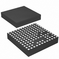
LTM4612MPV#PBF Linear Technology, LTM4612MPV#PBF Datasheet - Page 3

LTM4612MPV#PBF
Manufacturer Part Number
LTM4612MPV#PBF
Description
IC BUCK SYNC ADJ 5A 133LGA
Manufacturer
Linear Technology
Series
µModuler
Type
Point of Load (POL) Non-Isolatedr
Datasheet
1.LTM4612EVPBF.pdf
(26 pages)
Specifications of LTM4612MPV#PBF
Design Resources
LTM4612 Spice Model
Output
3.3 ~ 15 V
Number Of Outputs
1
Power (watts)
75W
Mounting Type
Surface Mount
Voltage - Input
5 ~ 36 V
Package / Case
133-LGA
1st Output
3.3 ~ 15 VDC @ 5A
Size / Dimension
0.59" L x 0.59" W x 0.11" H (15mm x 15mm x 2.8mm)
Power (watts) - Rated
75W
Operating Temperature
-55°C ~ 125°C
Lead Free Status / RoHS Status
Lead free / RoHS Compliant
3rd Output
-
2nd Output
-
Available stocks
Company
Part Number
Manufacturer
Quantity
Price
elecTrical characTerisTics
operating temperature range, otherwise specifications are at T
(front page) configuration.
SYMBOL
I
I
V
Output Specifications
I
DV
DV
V
V
f
DV
t
DV
t
I
Control Section
V
V
I
V
I
t
t
R
Q(VIN)
S(VIN)
OUT(DC)
S
START
SETTLE
OUT(PK)
SS / TRACK
FCB
ON(MIN)
OFF(MIN)
INTVCC
IN(AC)
OUT(AC)
FB
RUN
FCB
PLLIN
V
OUT(LINE)
OUT(LOAD)
OUT(START)
OUT(LS)
V
OUT
OUT
PARAMETER
Input Supply Bias Current
Input Supply Current
Internal V
Output Continuous Current Range
Line Regulation Accuracy
Load Regulation Accuracy
Input Ripple Voltage
Output Ripple Voltage
Output Ripple Voltage Frequency
Turn-On Overshoot,
TRACK/SS = 10nF
Turn-On Time, TRACK/SS = Open
Peak Deviation for Dynamic Load
Settling Time for Dynamic Load Step Load: 0% to 50% to 0% of Full Load, V
Output Current Limit
Voltage at V
RUN Pin On/Off Threshold
Soft-Start Charging Current
Forced Continuous Threshold
Forced Continuous Pin Current
Minimum On-Time
Minimum Off-Time
PLLIN Input Resistor
CC
FB
Voltage
Pin
CONDITIONS
V
V
Shutdown, RUN = 0, V
V
V
V
V
V
I
V
I
C
Electrolytic, 1 × 10µF X5R Ceramic on V
I
C
I
C
C
Resistive Load
Load: 0% to 50% to 0% of Full Load
C
C
I
V
V
(Note 3)
(Note 3)
OUT
OUT
OUT
OUT
OUT
IN
IN
IN
IN
IN
IN
OUT
OUT
IN
OUT
OUT
OUT
OUT
OUT
SS/TRACK
FCB
V
V
V
V
V
V
V
V
V
V
V
V
V
= 36V, V
= 24V, V
= 36V, V
= 24V, V
= 24V, V
= 2 × 10µF X5R Ceramic and 1 × 100µF
= 36V, RUN > 2V, I
IN
IN
IN
IN
IN
IN
IN
IN
IN
IN
IN
IN
IN
= 0A
= 0A,
= 0A,
= 1A, V
= 0A, V
= 0V
= 12V, FCB = 0V, V
= 12V, FCB = 0V, I
= 2 × 22µF , 2 × 47µF X5R Ceramic
= 200µF , V
= 300µF , V
= 2 × 22µF Ceramic, 150µF Bulk
= 200µF
The
= 36V
= 24V
= 24V, V
= 24V, V
= 24V, V
= 24V, V
= 36V
= 24V
= 36V
= 24V
= 24V, V
= 36V, V
= 24V, V
= 0V
A
OUT
OUT
OUT
OUT
OUT
l
IN
OUT
= 25°C, V
denotes the specifications which apply over the full internal
= 24V, V
OUT
OUT
OUT
OUT
OUT
OUT
OUT
OUT
OUT
= 12V, Switching Continuous
= 12V, Switching Continuous
= 12V, I
= 12V, I
= 12V (Note 4)
= 12V
= 5V
= 12V
= 5V
= 12V
= 12V
= 12V
= 12V
= 12V, I
= 12V, I
OUT
OUT
IN
OUT
OUT
OUT
IN
IN
= 36V
= 0A
= 22V to 36V,
= 12V
= 24V, unless otherwise noted. Per Typical Application
= 0A to 5A (Note 4)
OUT
OUT
= 5A
= 5A
= 0A
= 1A
IN
D
= 24V
Pins
l
l
l
l
0.591
MIN
0.57
4.7
–1
0
1
1.85
2.72
0.05
17.5
12.5
–1.5
TYP
940
153
250
0.3
0.3
7.2
3.4
0.5
0.5
0.6
1.5
0.6
57
48
50
20
20
37
–1
50
50
5
9
9
LTM4612
0.609
MAX
0.63
100
400
5.3
0.3
0.6
0.6
1.9
–2
–2
5
UNITS
mV
mV
mV
mV
4612fa
kHz
mA
mA
mV
mV
mV
ms
ms
P-P
P-P
P-P
P-P
kW
µA
µA
µA
µs
ns
ns
%
%
%
A
A
V
A
A
A
V
V
V


