TLRBP TDK Corporation, TLRBP Datasheet - Page 21
TLRBP
Manufacturer Part Number
TLRBP
Description
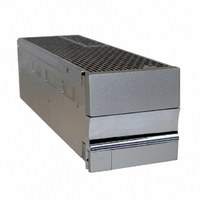
BLANKING PANEL
Manufacturer
TDK Corporation
Series
TLr
Specifications of TLRBP
Accessory Type
Blank Panel
For Use With
285-1646 - PWR SUP FNT END 48V 1000W 20A285-1645 - PWR SUP FNT END 24V 1000W 40A
Lead Free Status / RoHS Status
Lead free / RoHS Compliant
For Use With/related Products
TL Series
Lead Free Status / RoHS Status
Lead free / RoHS Compliant, Lead free / RoHS Compliant
Other names
285-1648


5.4 DC Reference ground
Connect your reference ground to either the negative output or positive output (Figure 10)
depending on the desired polarity. The connection is double ¼"-20 studs with 5/8" centers.
5.5 Alarms and control
Access to alarms and control signals is accomplished via a rear mounted connector (p/n 43045-
2019, Molex) as shown in Figure 12. Table 12 provides a pin functional description.
· The pin out of the alarm connector on the rack is a 180° difference from a standard Molex con-
nector. See Figure 11 & Figure 12.
· AC fail, DC fail, and Thermal limit fail alarms are all open collector, opto-coupled, active high
on failure/active low normally (software or factory configurable), and referenced to pin 17. The
pin is able to sink 10 mA of current at 5 V and 5 mA at TTL voltages.
· Applying 5 V between pins 16 and 17 will shut all power modules down. Removing the 5V will
cause the rectifier to power back up.
3055 Del Sol Blvd • San Diego, CA 92154 • 1-800-LAMBDA-4
Figure 11 - Cable routing holes
TLR5-S S ERIES POWER SYSTEM
Cable routing
Revision 1 : January 2006
holes
Page. 21
Related parts for TLRBP
Image
Part Number
Description
Manufacturer
Datasheet
Request
R

Part Number:
Description:
TDK DC to DC Converters, DC to AC Inverters
Manufacturer:
TDK Corporation
Datasheet:
Part Number:
Description:
TDK DC to DC Converters, DC to AC Inverters
Manufacturer:
TDK Corporation
Datasheet: