HW-FLYLEADS Xilinx Inc, HW-FLYLEADS Datasheet - Page 12
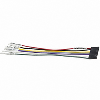
HW-FLYLEADS
Manufacturer Part Number
HW-FLYLEADS
Description
LEAD WIRES FLYING CABLE III/IV
Manufacturer
Xilinx Inc
Datasheet
1.HW-FLYLEADS.pdf
(20 pages)
Specifications of HW-FLYLEADS
Accessory Type
Parallel Cable
For Use With/related Products
Xilinx FPGA, CPLDS, Platform Flash PROMs, XC18V00 PROMs, System ACE MPM
Lead Free Status / RoHS Status
Contains lead / RoHS non-compliant
Other names
122-1473
Available stocks
Company
Part Number
Manufacturer
Quantity
Price


Target Reference Voltage Sensing (V
Platform Cable USB incorporates an over-voltage clamp on
the V
clamped voltage (V
(NC7SZ125) that drives each of the three output signals.
V
Note:
between the VREF supply and pin 2 on the 2 mm connector.
No damage to Platform Cable USB occurs if the A-B cable
is unplugged from the host while the ribbon cable or flying
leads are attached to a powered target system. Similarly, no
damage to target systems occurs if Platform Cable USB is
powered and attached to the target system while the target
system power is off.
Buffers for the output signals (TCK_CCLK_SCK,
TMS_PROG_SS, and TDI_DIN_MOSI) are set to high-Z
when V
linearly tracks voltage changes on the V
1.40V ≤ V
approximately 3.30V when 3.30 ≤ V
Refer to
and output signal amplitude.
Table 4: Output Signal Level as a Function of the V
Xilinx applications actively drive the outputs to logic 1 before
setting the respective buffer to high-Z, avoiding the
possibility of a slow rise-time transition caused by a charge
path through the pull-up resistor into parasitic capacitance
on the target system.
Output Driver Structure
Platform Cable USB drives three target signals:
TCK_CCLK_SCK, TMS_PROG_SS, and TDI_DIN_MOSI.
Each of these signals incorporates the same driver
topology. A Xilinx XC2C256 Coolrunner-II CPLD generates
the output signals.
Each signal is routed to an external NC7SZ125 high-speed
CMOS buffer
reduce reflections. Weak pull-up resistors (20 kΩ) maintain
DS300 (v3.2) May 14, 2008
Product Specification
Notes:
1.
REF
V
REF
There are weak pull-up resistors to VREF_A on each of the three
output drivers (TCK_CCLK_SCK, TMS_PROG_SS, and
TDI_DIN_MOSI). The output drivers are active only during
configuration and programming operations. Between operations,
the drivers are set to high-Z.
0.00 ≤ V
1.40 ≤ V
3.30 ≤ V
REF
must be a regulated voltage.
System (VDC)
Do not insert a current-limiting resistor in the target system
Voltage on Target
REF
Table 4
pin of the 2 mm ribbon cable connector. The
REF
drops below 1.40V. The output buffer amplitude
REF
REF
REF
R
(Figure
≤ 3.30V. Amplitude is clamped at
< 1.40
< 3.30
≤ 5.00
for the relationship between V
REF_A
22). Series-damping resistors (30Ω)
) supplies a high-slew-rate buffer
Output Signal
Levels (VDC)
High-Z
V
≅ 3.3
REF
REF
REF
≤ 5.00V.
pin when
Status LED
REF
Amber
Color
Green
Green
voltage
REF
www.xilinx.com
REF
)
a defined logic level when the buffers are set to high-Z. The
pull-up resistors terminate to V
X-Ref Target - Figure 22
Refer to
V
X-Ref Target - Figure 23
Input Receiver Structure
A Schottky diode is used to protect the TDO_DONE_MISO
voltage comparator
USB looks for voltages below V
tolerates voltages much higher than V
could be terminated to a supply other than V
X-Ref Target - Figure 24
Three-State
REF_A
Internal
Control
Figure 24: Target Interface Receiver Topology
CPLD
CPLD
Figure 22: Target Interface Driver Topology
as a function of V
Figure 23: V
Figure 23
I/O
I/O
V
High-Z
CC33_SW
LT1719
to determine the expected value of
(Figure
REF_A
V
V
REF
CC33
REF_A
as a Function of V
24). In effect, Platform Cable
NC7SZ125
.
V
REF_A
IL
REF_A
MAX to detect logic 0, and
.
BAT54
Platform Cable USB
REF_A
V
REF_A
DS300_22_113004
2 mm Connector
because TDO
REF
2 mm Connector
XFCE PIN
REF
DS300_22_120904
XFCE PIN
.
DS300_23_120904
12
Related parts for HW-FLYLEADS
Image
Part Number
Description
Manufacturer
Datasheet
Request
R

Part Number:
Description:
BOARD ADAPTER AND FLY LEADS
Manufacturer:
Xilinx Inc
Datasheet:

Part Number:
Description:
CONN HEADER .25" VERT 4POS T/H
Manufacturer:
Samtec Inc
Part Number:
Description:
CONN HEADER .25" VERT 4POS SMD
Manufacturer:
Samtec Inc
Part Number:
Description:
CONN HEADER .25" VERT 10POS SMD
Manufacturer:
Samtec Inc
Part Number:
Description:
Conn Board Stacker HDR 28 POS 2.54mm Solder ST SMD
Manufacturer:
Samtec Inc
Datasheet:
Part Number:
Description:
CONN BOARD STACK 28POS SMD
Manufacturer:
Samtec Inc
Datasheet:

Part Number:
Description:
IC CPLD .8K 36MCELL 44-VQFP
Manufacturer:
Xilinx Inc
Datasheet:

Part Number:
Description:
IC CPLD 72MCRCELL 10NS 44VQFP
Manufacturer:
Xilinx Inc
Datasheet:

Part Number:
Description:
IC CPLD 1.6K 72MCELL 64-VQFP
Manufacturer:
Xilinx Inc
Datasheet:

Part Number:
Description:
IC CR-II CPLD 64MCELL 44-VQFP
Manufacturer:
Xilinx Inc
Datasheet:

Part Number:
Description:
IC CPLD 1.6K 72MCELL 100-TQFP
Manufacturer:
Xilinx Inc
Datasheet:

Part Number:
Description:
IC CR-II CPLD 64MCELL 56-BGA
Manufacturer:
Xilinx Inc
Datasheet: