AC164112 Microchip Technology, AC164112 Datasheet - Page 142
AC164112
Manufacturer Part Number
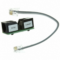
AC164112
Description
VOLTAGE LIMITER MPLAB ICD2 VPP
Manufacturer
Microchip Technology
Datasheet
1.AC164112.pdf
(302 pages)
Specifications of AC164112
Accessory Type
Voltage Limiter
Product
Cable Assemblies
Features
Programming And Debugging The Latest PIC12/PIC16/PIC18 Products
Development Tool Type
Hardware - Eval/Demo Board
Lead Free Status / RoHS Status
Lead free / RoHS Compliant
For Use With/related Products
MPLAB®
Lead Free Status / Rohs Status
Lead free / RoHS Compliant
For Use With
MPLAB ICD 2
Lead Free Status / RoHS Status
Lead free / RoHS Compliant, Lead free / RoHS Compliant
Available stocks
Company
Part Number
Manufacturer
Quantity
Price
Company:

Part Number:
AC164112
Manufacturer:
Microchip Technology
Quantity:
135


PIC16F72X/PIC16LF72X
15.3.2
The PWM period is specified by the PR2 register of
Timer2. The PWM period can be calculated using the
formula of Equation 15-1.
EQUATION 15-1:
When TMR2 is equal to PR2, the following three events
occur on the next increment cycle:
• TMR2 is cleared
• The CCPx pin is set. (Exception: If the PWM duty
• The PWM duty cycle is latched from CCPRxL into
15.3.3
The PWM duty cycle is specified by writing a 10-bit value
to multiple registers: CCPRxL register and DCxB<1:0>
bits of the CCPxCON register. The CCPRxL contains
the eight MSbs and the DCxB<1:0> bits of the
CCPxCON register contain the two LSbs. CCPRxL and
DCxB<1:0> bits of the CCPxCON register can be written
to at any time. The duty cycle value is not latched into
CCPRxH until after the period completes (i.e., a match
between PR2 and TMR2 registers occurs). While using
the PWM, the CCPRxH register is read-only.
Equation 15-2 is used to calculate the PWM pulse
width.
Equation 15-3 is used to calculate the PWM duty cycle
ratio.
DS41341E-page 142
cycle = 0%, the pin will not be set.)
CCPRxH.
Note:
Note:
PWM Period
PWM PERIOD
The
Section 13.1 “Timer2 Operation”) is not
used in the determination of the PWM
frequency.
PWM DUTY CYCLE
T
OSC
Timer2
=
= 1/F
(TMR2 Prescale Value)
[
PWM PERIOD
(
PR2
OSC
)
+
postscaler
1
] 4 T
•
•
OSC
(refer
•
to
EQUATION 15-2:
EQUATION 15-3:
The CCPRxH register and a 2-bit internal latch are
used to double buffer the PWM duty cycle. This double
buffering is essential for glitchless PWM operation.
The 8-bit timer TMR2 register is concatenated with
either the 2-bit internal system clock (F
the prescaler, to create the 10-bit time base. The system
clock is used if the Timer2 prescaler is set to 1:1.
When the 10-bit time base matches the CCPRxH and
2-bit latch, then the CCPx pin is cleared (refer to
Figure 15-3).
Duty Cycle Ratio
Pulse Width
Note: T
OSC
=
= 1/F
(
T
=
CCPRxL:CCPxCON<5:4>
OSC
OSC
PULSE WIDTH
DUTY CYCLE RATIO
(
---------------------------------------------------------------------- -
CCPRxL:CCPxCON<5:4>
© 2009 Microchip Technology Inc.
•
(TMR2 Prescale Value)
4 PR2
(
+
OSC
1
)
), or 2 bits of
)
•
)
Related parts for AC164112
Image
Part Number
Description
Manufacturer
Datasheet
Request
R

Part Number:
Description:
Manufacturer:
Microchip Technology Inc.
Datasheet:
Part Number:
Description:
Manufacturer:
Microchip Technology Inc.
Datasheet:
Part Number:
Description:
Manufacturer:
Microchip Technology Inc.
Datasheet:
Part Number:
Description:
Manufacturer:
Microchip Technology Inc.
Datasheet:
Part Number:
Description:
Manufacturer:
Microchip Technology Inc.
Datasheet:
Part Number:
Description:
Manufacturer:
Microchip Technology Inc.
Datasheet:
Part Number:
Description:
Manufacturer:
Microchip Technology Inc.
Datasheet:
Part Number:
Description:
Manufacturer:
Microchip Technology Inc.
Datasheet: