AC164112 Microchip Technology, AC164112 Datasheet - Page 38
AC164112
Manufacturer Part Number
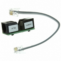
AC164112
Description
VOLTAGE LIMITER MPLAB ICD2 VPP
Manufacturer
Microchip Technology
Datasheet
1.AC164112.pdf
(302 pages)
Specifications of AC164112
Accessory Type
Voltage Limiter
Product
Cable Assemblies
Features
Programming And Debugging The Latest PIC12/PIC16/PIC18 Products
Development Tool Type
Hardware - Eval/Demo Board
Lead Free Status / RoHS Status
Lead free / RoHS Compliant
For Use With/related Products
MPLAB®
Lead Free Status / Rohs Status
Lead free / RoHS Compliant
For Use With
MPLAB ICD 2
Lead Free Status / RoHS Status
Lead free / RoHS Compliant, Lead free / RoHS Compliant
Available stocks
Company
Part Number
Manufacturer
Quantity
Price
Company:

Part Number:
AC164112
Manufacturer:
Microchip Technology
Quantity:
135


PIC16F72X/PIC16LF72X
3.6
On power-up, the time-out sequence is as follows: first,
PWRT time-out is invoked after POR has expired, then
OST is activated after the PWRT time-out has expired.
The total time-out will vary based on oscillator configu-
ration and PWRTE bit status. For example, in EC mode
with PWRTE bit = 1 (PWRT disabled), there will be no
time-out at all. Figure 3-4, Figure 3-5 and Figure 3-6
depict time-out sequences.
Since the time-outs occur from the POR pulse, if MCLR
is kept low long enough, the time-outs will expire. Then,
bringing MCLR high will begin execution immediately
(see Figure 3-5). This is useful for testing purposes or
to
PIC16LF72X device operating in parallel.
Table 3-3 shows the Reset conditions for some special
registers.
TABLE 3-2:
TABLE 3-3:
DS41341E-page 38
XT, HS, LP
RC, EC, INTOSC
Note 1:
Legend: u = unchanged, x = unknown
Oscillator Configuration
POR
synchronize
0
1
u
u
u
u
Time-out Sequence
LP mode with T1OSC disabled.
(1)
BOR
u
0
u
u
u
u
TIME-OUT IN VARIOUS SITUATIONS
RESET BITS AND THEIR SIGNIFICANCE
more
TO
1
1
0
0
u
1
than
T
PWRT
PWRTE = 0
T
one
T
PWRT
PD
OSC
1
1
u
0
u
0
+ 1024 •
PIC16F72X/
Power-up
Power-on Reset
Brown-out Reset
WDT Reset
WDT Wake-up
MCLR Reset during normal operation
MCLR Reset during Sleep
1024 • T
PWRTE = 1
—
OSC
indicating that a Brown-out has occurred. The BOR
Status bit is a “don’t care” and is not necessarily
predictable if the brown-out circuit is disabled
3.7
The Power Control (PCON) register has two Status bits
to indicate what type of Reset that last occurred.
Bit 0 is BOR (Brown-out Reset). BOR is unknown on
Power-on Reset. It must then be set by the user and
checked on subsequent Resets to see if BOR = 0,
(BOREN<1:0> = 00 in the Configuration Word register).
Bit 1 is POR (Power-on Reset). It is a ‘0’ on Power-on
Reset and unaffected otherwise. The user must write a
‘1’ to this bit following a Power-on Reset. On a
subsequent Reset, if POR is ‘0’, it will indicate that a
Power-on Reset has occurred (i.e., V
gone too low).
For more information, see Section 3.5 “Brown-Out
Reset (BOR)”.
T
PWRT
PWRTE = 0
T
T
PWRT
Power Control (PCON) Register
OSC
+ 1024 •
Brown-out Reset
Condition
PWRTE = 1
1024 • T
© 2009 Microchip Technology Inc.
—
OSC
Wake-up from
1024 • T
DD
Sleep
may have
—
OSC
Related parts for AC164112
Image
Part Number
Description
Manufacturer
Datasheet
Request
R

Part Number:
Description:
Manufacturer:
Microchip Technology Inc.
Datasheet:
Part Number:
Description:
Manufacturer:
Microchip Technology Inc.
Datasheet:
Part Number:
Description:
Manufacturer:
Microchip Technology Inc.
Datasheet:
Part Number:
Description:
Manufacturer:
Microchip Technology Inc.
Datasheet:
Part Number:
Description:
Manufacturer:
Microchip Technology Inc.
Datasheet:
Part Number:
Description:
Manufacturer:
Microchip Technology Inc.
Datasheet:
Part Number:
Description:
Manufacturer:
Microchip Technology Inc.
Datasheet:
Part Number:
Description:
Manufacturer:
Microchip Technology Inc.
Datasheet: