ATSTK524 Atmel, ATSTK524 Datasheet - Page 9
ATSTK524
Manufacturer Part Number
ATSTK524
Description
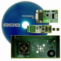
KIT STARTER ATMEGA32M1/MEGA32C1
Manufacturer
Atmel
Datasheet
1.ATSTK524.pdf
(20 pages)
Specifications of ATSTK524
Accessory Type
Daughter Board
For Use With/related Products
STK500
For Use With
ATSTK500 - PROGRAMMER AVR STARTER KIT
Lead Free Status / RoHS Status
Lead free / RoHS Compliant


4.3
7780A–AVR–02/08
JTAGICE mkII Connector
To program the AVR using High-voltage (Parallel) Programming, connect the PROGCTRL to
PORTD and PROGDATA to PORTB on the STK500 as shown in
TOSC-switch is placed in the XTAL position.
The STK500 & STK524 jumpers must follow the configuration :
Table 6-1. High-Voltage programming jumper settings for ATmega32M1/C1
The device can now be programmed using the High-voltage Programming mode in AVR Studio
STK500 software.
Note:
Note:
See the following document :
“JTAGICE mkII Quick Start Guide” which purpose is “Connecting to a target board with the AVR
JTAGICE mkII”.
This note explains which signals are required for ISP and which signals are required for
debugWIRE.
Figure 4-3
See the STK500 User Guide for information on how to use the STK500 front-end software in High-
voltage Programming mode.
For the High-voltage Programming mode to function correctly, the target voltage must be higher
than 4.5V.
shows how to connect the JTAGICE mkII probe on the STK524 board.
VTARGET
OSCSEL
STK500
STK524
RESET
PJUMP
BSEL2
XTAL1
AREF
VTG
Mounted, pin 1 and 2
Mounted
Mounted
Mounted
Mounted
Mounted
Optional
Open
Figure
4-2. Make sure that the
AVR078
9
Related parts for ATSTK524
Image
Part Number
Description
Manufacturer
Datasheet
Request
R

Part Number:
Description:
DEV KIT FOR AVR/AVR32
Manufacturer:
Atmel
Datasheet:

Part Number:
Description:
INTERVAL AND WIPE/WASH WIPER CONTROL IC WITH DELAY
Manufacturer:
ATMEL Corporation
Datasheet:
Part Number:
Description:
Low-Voltage Voice-Switched IC for Hands-Free Operation
Manufacturer:
ATMEL Corporation
Datasheet:
Part Number:
Description:
MONOLITHIC INTEGRATED FEATUREPHONE CIRCUIT
Manufacturer:
ATMEL Corporation
Datasheet:
Part Number:
Description:
AM-FM Receiver IC U4255BM-M
Manufacturer:
ATMEL Corporation
Datasheet:
Part Number:
Description:
Monolithic Integrated Feature Phone Circuit
Manufacturer:
ATMEL Corporation
Datasheet:
Part Number:
Description:
Multistandard Video-IF and Quasi Parallel Sound Processing
Manufacturer:
ATMEL Corporation
Datasheet:
Part Number:
Description:
High-performance EE PLD
Manufacturer:
ATMEL Corporation
Datasheet:
Part Number:
Description:
8-bit Flash Microcontroller
Manufacturer:
ATMEL Corporation
Datasheet:
Part Number:
Description:
2-Wire Serial EEPROM
Manufacturer:
ATMEL Corporation
Datasheet: