MAXSPCSPARTAN6+ Maxim Integrated Products, MAXSPCSPARTAN6+ Datasheet

ADC and DAC Eval Expansion Board

MAXSPCSPARTAN6+

Manufacturer Part Number
MAXSPCSPARTAN6+
Description
ADC and DAC Eval Expansion Board
Manufacturer
Maxim Integrated Products
Series
Spartan®-6r
Type
A/Dr
Datasheet

Specifications of MAXSPCSPARTAN6+

Accessory Type
ADC & DAC Eval Expansion Board
Resolution
12 bit, 24 bit
Maximum Clock Frequency
24.576 MHz
Interface Type
SPI
Supply Voltage (max)
5 V
Product
Data Conversion Development Tools
For Use With/related Products
MAX11612, MAX11040, MAX5135, Xilinx® Spartan® 6 Series FPGAs
Lead Free Status / RoHS Status
Lead free / RoHS Compliant
19-5283; Rev 0; 5/10
The MAXSPCSPARTAN6+ evaluation kit (EV kit) is
designed to facilitate the use of Maxim ADCs and DACs
with any evaluation board made for Xilinx
6 series FPGAs. The EV kit contains the MAX11612 and
MAX11040 ADCs and two cascaded MAX5135 DACs.
The MAX11612 is a very-low-power, 4-channel, 2-wire,
12-bit, SAR ADC. This ADC operates with a 5V supply
and has an internal reference of 4.096V.
The MAX11040 is an SPIK-compatible, 4-channel,
simultaneous-sampling, cascadable, 24-bit, sigma-delta
ADC. The MAX5135 is the industry’s smallest, 12-bit,
voltage-output DAC.
Xilinx and Spartan are registered trademarks of Xilinx.
SPI is a trademark of Motorola, Inc.
µMAX is a registered trademark of Maxim Integrated Products,
Inc.
For pricing, delivery, and ordering information, please contact Maxim Direct at 1-888-629-4642,
or visit Maxim’s website at www.maxim-ic.com.
DESIGNATION
C4, C15–C20,
D3, D4, D5
C11–C14,
C21–C26,
C27, C28
C33, C34
C35, C36
C29–C32
C7–C10
C2, C3,
C5, C6
D1, D2
J3, J4
J6, J7
C1
J1
J2
J5
________________________________________________________________ _Maxim Integrated Products_ _ 1
QTY
16
1
9
2
4
2
2
2
3
1
1
2
1
2
General Description
10FF Q20%, 25V ceramic
capacitor (1206)
0.1FF Q10%, 50V ceramic
capacitors (0603)
1FF Q10%, 25V ceramic
capacitors (0603)
18pF Q5%, 50V C0G ceramic
capacitors (0603)
0.01FF Q5%, 25V ceramic
capacitors (0603)
47pF, 50V ceramic capacitors
(0603)
4.7FF Q10%, 10V ceramic
capacitors (0603)
Orange SMT LEDs (0603)
Green SMT LEDs (0603)
FMC LPC connector (VITA-57.1)
8 x 2-pin R/A header (2.54mm)
8 x 2-pin headers (2.54mm)
8-pin inline receptacle, 0.1in
centers
3-pin headers (2.54mm)
MAXSPCSPARTAN6+ Evaluation Kit
DESCRIPTION
M
Spartan
M
S
S
S
S
+Denotes lead(Pb)-free and RoHS compliant.
*EP = Exposed pad.
MAXSPCSPARTAN6+
DESIGNATION
R15, R21–R24
R18, R19, R20
12-Bit,_2-/4-Channel,_SAR_ADC_Support_
(MAX11612)
24-Bit,_4-Channel,_Programmable_Data_Rate,_
Sigma-Delta_ADC_Support_(MAX11040)
12-Bit,_4-Channel_DAC_Support_(MAX5135)
Connects_with_any_Spartan_6_Evaluation_Boards_
Through_a_Standard_FMC_VITA-57.1_LPC_
Connector
R1, R2, R16,
R11–R14
R3–R10
U6, U7
R17
U1
U2
U3
U4
U5
Y1
L1
PART
QTY
1
4
8
4
5
3
1
1
1
1
1
2
1
1
Ordering Information
10FH Q5% inductor (0603, 0)
2.2kI Q5% resistors (0603)
49.9I Q0.1% resistors (0603)
100I Q1% resistors (0603)
4.7kI Q0.1% resistors (0603)
0I Q1% resistors (0603)
Step-down converter (6 SOT23)
Maxim MAX1837EUT50#G16
Low-power ADC (8 FMAX
Maxim MAX11612EUA+
Sigma-delta ADC (38 TSSOP)
Maxim MAX11040GUU+
Bidirectional level translator
(12 TQFN-EP*)
Maxim MAX3395EETC+
8-channel level translator
(20 TSSOP)
Maxim MAX3002EUP
Quad 12-bit DACs (24 TQFN-EP*)
Maxim MAX5135GTG+
24.576MHz, 18pF crystal
PCB: MAXSPCSPARTAN6+
Component List
DESCRIPTION
EV Kit
TYPE
Features
M
)

Related parts for MAXSPCSPARTAN6+

MAXSPCSPARTAN6+ Summary of contents

Page 1

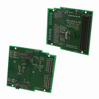
... Rev 0; 5/10 MAXSPCSPARTAN6+ Evaluation Kit General Description The MAXSPCSPARTAN6+ evaluation kit (EV kit) is designed to facilitate the use of Maxim ADCs and DACs with any evaluation board made for Xilinx 6 series FPGAs. The EV kit contains the MAX11612 and MAX11040 ADCs and two cascaded MAX5135 DACs. ...

Page 2

... MAXSPCSPARTAN6+ Evaluation Kit The MAXSPCSPARTAN6+ board can be plugged in to any Spartan 6 series FPGA evaluation board. A two-step configuration is needed to use this card with the FPGA evaluation board: 1) Place a shunt on pins 2-3 of header J7 (i.e., +3V3FMC to +3V3). 2) Place a shunt on pins 2-3 of header J6 (i.e., +5VREG to +5V). ...

Page 3

... MAXSPCSPARTAN6+ Evaluation Kit Table_2._MAXSPCSPARTAN6+_Connector_ J3_Description J3_PIN_NO. LABEL +5V, 250mA supply for external 1 +5V circuit 2 N.C. Not connected ADC negative input to channel 3 AD3 (MAX11040) ADC positive input to channel 3 4 AD3 (MAX11040) ADC negative input to channel 5 AD2 (MAX11040) ADC positive input to channel 2 6 AD2+ ...

Page 4

... MAXSPCSPARTAN6+ Evaluation Kit Figure 1a. MAXSPCSPARTAN6+ EV Kit Schematic (Sheet _______________________________________________________________________________________ ...

Page 5

... MAXSPCSPARTAN6+ Evaluation Kit Figure 1b. MAXSPCSPARTAN6+ EV Kit Schematic (Sheet ________________________________________________________________________________________ _ 5 ...

Page 6

... MAXSPCSPARTAN6+ Evaluation Kit Figure 1c. MAXSPCSPARTAN6+ EV Kit Schematic (Sheet _______________________________________________________________________________________ ...

Page 7

... MAXSPCSPARTAN6+ Evaluation Kit Figure 1d. MAXSPCSPARTAN6+ EV Kit Schematic (Sheet ________________________________________________________________________________________ _ 7 ...

Page 8

... MAXSPCSPARTAN6+ Evaluation Kit Figure 2. MAXSPCSPARTAN6+ Component Placement Guide—Component Side Figure 3. MAXSPCSPARTAN6+ Component Placement Guide—Solder Side 8_ _ _______________________________________________________________________________________ Figure 4. MAXSPCSPARTAN6+ PCB Layout—Component Side Figure 5. MAXSPCSPARTAN6+ PCB Layout—Solder Side ...

Page 9

... MAXSPCSPARTAN6+ Evaluation Kit REVISION REVISION_ NUMBER DATE 0 5/10 Initial release Maxim cannot assume responsibility for use of any circuitry other than circuitry entirely embodied in a Maxim product. No circuit patent licenses are implied. Maxim reserves the right to change the circuitry and specifications without notice at any time. ...

Related keywords