MAXSPCSPARTAN6+ Maxim Integrated Products, MAXSPCSPARTAN6+ Datasheet - Page 2
MAXSPCSPARTAN6+
Manufacturer Part Number
MAXSPCSPARTAN6+
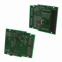
Description
ADC and DAC Eval Expansion Board
Manufacturer
Maxim Integrated Products
Series
Spartan®-6r
Type
A/Dr
Datasheet
1.MAXSPCSPARTAN6.pdf
(9 pages)
Specifications of MAXSPCSPARTAN6+
Accessory Type
ADC & DAC Eval Expansion Board
Resolution
12 bit, 24 bit
Maximum Clock Frequency
24.576 MHz
Interface Type
SPI
Supply Voltage (max)
5 V
Product
Data Conversion Development Tools
For Use With/related Products
MAX11612, MAX11040, MAX5135, Xilinx® Spartan® 6 Series FPGAs
Lead Free Status / RoHS Status
Lead free / RoHS Compliant


MAXSPCSPARTAN6+ Evaluation Kit
The MAXSPCSPARTAN6+ board can be plugged in to
any Spartan 6 series FPGA evaluation board. A two-step
configuration is needed to use this card with the FPGA
evaluation board:
1)
2)
Now connect the MAXSPCSPARTAN6+ board to the
FPGA EV kit. On power-up, LEDs D3, D4, and D5 should
glow, indicating a power-up state.
The MAXSPCSPARTAN6+ board is loaded with Maxim’s
ADCs and DACs and makes it very easy to integrate the
FPGA with any analog interface.
The MAX11612 is a 12-bit, 2-/4-channel, I
ADC. The FPGA can drive commands for data
acquisition from the MAX11612 on the I
0110100. The MAX11612 can work with the internal
reference of 4.096V or the external reference connected
at the AD3 port of J2. If internal reference is used; all
4 channels can be sampled from AD0–AD3. For more
information, refer to the MAX11612 IC data sheet.
The MAX11040 is a 24-bit, 4-channel, SPI-compatible,
sigma-delta ADC with programmable output data rate.
It has an internal reference of 2.5V with Q2.2V input
range. Input ports are marked as AD0-/AD0+ to AD3-/
AD3+ on J3. External reference can also be applied. The
MAX11040 does simultaneous sampling and data for all
4 channels and can be acquired in one read.
This ADC has four standard connections for SPI
communication. It also has an extra signal (DRDYOUT)
that interrupts the FPGA at every end-of-conversion
to sample the data. For more information, refer to the
MAX11040 IC data sheet.
The MAX5135 is a 12-bit, 4-channel, voltage output,
SPI-compatible DAC. The MAXSPCSPARTAN6+ board
contains two MAX5135 ICs in a cascaded configura-
tion. The DAC channels are marked as DA0–DA3 on J2
and DA4–DA7 on J3. For more information, refer to the
MAX5135 IC data sheet.
2_ _ _______________________________________________________________________________________
Detailed Description of Hardware
Place a shunt on pins 2-3 of header J7
(i.e., +3V3FMC to +3V3).
Place a shunt on pins 2-3 of header J6
(i.e., +5VREG to +5V).
Communication with the MAX11612
Communication with the MAX11040
Communication with the MAX5135
Quick Start
2
C slave address
2
C-compatible
Table_1._MAXSPCSPARTAN6+_Connector_
J2_Description
J2_PIN_NO.
10
11
12
13
14
15
16
1
2
3
4
5
6
7
8
9
LABEL
GND
GND
GND
GND
GND
N.C.
DA0
DA1
DA2
DA3
AD1
AD0
AD3
AD2
+5V
I/O
+5V, 250mA supply for external
circuit
Not connected
Ground
DAC output from channel 0 of U6
(MAX5135)
Ground
DAC output from channel 1 of U6
(MAX5135)
Ground
DAC output from channel 2 of U6
(MAX5135)
Ground
DAC output from channel 3 of U6
(MAX5135)
ADC input to channel 1 of U2
(MAX11612)
ADC input to channel 0 of U2
(MAX11612)
Ground
Digital input/output connected to
FMC connector at C18
ADC input to channel 3 of U2
(MAX11612)
ADC input to channel 2 of U2
(MAX11612)
FUNCTION
Related parts for MAXSPCSPARTAN6+
Image
Part Number
Description
Manufacturer
Datasheet
Request
R

Part Number:
Description:
MAX7528KCWPMaxim Integrated Products [CMOS Dual 8-Bit Buffered Multiplying DACs]
Manufacturer:
Maxim Integrated Products
Datasheet:
Part Number:
Description:
Single +5V, fully integrated, 1.25Gbps laser diode driver.
Manufacturer:
Maxim Integrated Products
Datasheet:
Part Number:
Description:
Single +5V, fully integrated, 155Mbps laser diode driver.
Manufacturer:
Maxim Integrated Products
Datasheet:
Part Number:
Description:
VRD11/VRD10, K8 Rev F 2/3/4-Phase PWM Controllers with Integrated Dual MOSFET Drivers
Manufacturer:
Maxim Integrated Products
Datasheet:
Part Number:
Description:
Highly Integrated Level 2 SMBus Battery Chargers
Manufacturer:
Maxim Integrated Products
Datasheet:
Part Number:
Description:
Current Monitor and Accumulator with Integrated Sense Resistor; ; Temperature Range: -40°C to +85°C
Manufacturer:
Maxim Integrated Products
Part Number:
Description:
TSSOP 14/A�/RS-485 Transceivers with Integrated 100O/120O Termination Resis
Manufacturer:
Maxim Integrated Products
Part Number:
Description:
TSSOP 14/A�/RS-485 Transceivers with Integrated 100O/120O Termination Resis
Manufacturer:
Maxim Integrated Products
Part Number:
Description:
QFN 16/A�/AC-DC and DC-DC Peak-Current-Mode Converters with Integrated Step
Manufacturer:
Maxim Integrated Products
Part Number:
Description:
TDFN/A/65V, 1A, 600KHZ, SYNCHRONOUS STEP-DOWN REGULATOR WITH INTEGRATED SWI
Manufacturer:
Maxim Integrated Products
Part Number:
Description:
Integrated Temperature Controller f
Manufacturer:
Maxim Integrated Products
Part Number:
Description:
SOT23-6/I�/45MHz to 650MHz, Integrated IF VCOs with Differential Output
Manufacturer:
Maxim Integrated Products
Part Number:
Description:
SOT23-6/I�/45MHz to 650MHz, Integrated IF VCOs with Differential Output
Manufacturer:
Maxim Integrated Products
Part Number:
Description:
EVALUATION KIT/2.4GHZ TO 2.5GHZ 802.11G/B RF TRANSCEIVER WITH INTEGRATED PA
Manufacturer:
Maxim Integrated Products
Part Number:
Description:
QFN/E/DUAL PCIE/SATA HIGH SPEED SWITCH WITH INTEGRATED BIAS RESISTOR
Manufacturer:
Maxim Integrated Products
Datasheet: