OM11005 NXP Semiconductors, OM11005 Datasheet
OM11005
Specifications of OM11005


Related parts for OM11005


OM11005 Summary of contents
Page 1
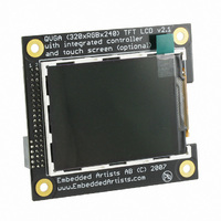
QVGA TFT Color LCD Copyright 2007 © Embedded Artists AB 3.2 inch QVGA TFT Color LCD User’s Guide Give graphics and color to your application! - User’s Guide Version 1 & 2 EA2-USG-0701 v2.1 Rev A ...
Page 2
QVGA TFT Color LCD - User’s Guide Embedded Artists AB Ole Römers väg 12 SE-223 70 Lund Sweden info@EmbeddedArtists.com http://www.EmbeddedArtists.com Copyright 2005-2007 © Embedded Artists AB. All rights reserved. No part of this publication may be reproduced, transmitted, ...
Page 3
QVGA TFT Color LCD - User’s Guide Copyright 2007 © Embedded Artists AB Table of Contents 1 Introduction 1.1 Features 1.2 Version 1 vs. Version 2 1.3 ESD Precaution 1.4 Other Products from Embedded Artists 1.4.1 Design and ...
Page 4
QVGA TFT Color LCD - User’s Guide 1 Introduction Thank you for buying Embedded Artists’ 3.2 inch QVGA TFT Color LCD Board based on a LCD from Truly. Sample applications for our NXP LPC2xxx based boards are also ...
Page 5
QVGA TFT Color LCD - User’s Guide extra signals for direct RGB-control of display (useful when interfacing the LPC2478 MCU from NXP). 1.3 ESD Precaution Always take ESD precaution when handling the QVGA LCD Module. Components are exposed ...
Page 6
QVGA TFT Color LCD - User’s Guide 2 Design Description This chapter describes the hardware design of the QVGA LCD Board. 2.1 Backlight Control White LEDs are used as backlight on the display. The LED current is set ...
Page 7
QVGA TFT Color LCD - User’s Guide 3-wire 4-wire serial serial SPI i Does not matter. This pin is currently not used. Does not matter. This pin is ...
Page 8
QVGA TFT Color LCD - User’s Guide 16 bit 16 bit parallel parallel 18-bit 18-bit color color depth depth (9+9) (16+ Does not matter. This pin is currently ...
Page 9
QVGA TFT Color LCD - User’s Guide 5 CFG2 / DTX1 interface configuration pin (see description above) 6 CFG3 / DTX2 interface configuration pin (see description above) 7 CFG4 / BWS0 interface configuration pin (see description above) 8 ...
Page 10
QVGA TFT Color LCD - User’s Guide The picture below illustrates the pin numbering of the QVGA LCD Module. Pin1 Pin2 On V2 Pin: Pin40 Figure 1 - 3.2 inch QVGA TFT Color ...
Page 11
QVGA TFT Color LCD - User’s Guide 2.6 Optimum Viewing Angle Optimum viewing angles are as illustrated below. Figure 2 - 3.2 inch QVGA TFT Color LCD Board Optimum Viewing Angle Copyright 2007 © Embedded Artists AB Page ...
Page 12
QVGA TFT Color LCD - User’s Guide 2.7 Connecting version 2 to OEM Base Board < v1.5 Version 1.5 and above of the OEM Base Board has direct connectors for all 46 positions in the interface connector. Version ...
Page 13
QVGA TFT Color LCD - User’s Guide Figure 4 – Picture of Wire to Pin 45 on Display Module Figure 5 – Wire to p0.16 on OEM Base Board Copyright 2007 © Embedded Artists AB Three SPI jumpers ...
Page 14
QVGA TFT Color LCD - User’s Guide 3 Board Mechanical Dimensions Figure 6 below contains a drawing of the board that includes mechanical measures. Four 4.3 mm grounded mounting holes are used. 2x2.54 mm 10.7 mm Only on ...
Page 15
QVGA TFT Color LCD - User’s Guide 4 Product Registration You can download a lot of valuable information and programs that will easy your program development from the support pages. See details below about the product registration process, ...