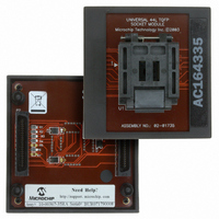
AC164335 Microchip Technology, AC164335 Datasheet - Page 214
AC164335
Manufacturer Part Number
AC164335
Description
MODULE SKT FOR 10X10 PM3 44TQFP
Manufacturer
Microchip Technology
Datasheet
1.AC164335.pdf
(286 pages)
Specifications of AC164335
Module/board Type
Socket Module - TQFP
Product
Microcontroller Accessories
Lead Free Status / RoHS Status
Not applicable / Not applicable
For Use With/related Products
MPLAB® PM3
For Use With
DV007003 - PROGRAMMER UNIVERSAL PROMATE II
Lead Free Status / RoHS Status
Lead free / RoHS Compliant, Not applicable / Not applicable


dsPIC30F1010/202X
FIGURE 18-10:
18.7.1.1
The oscillator start-up circuitry is not linked to the POR
circuitry.
frequency crystals) will have a relatively long start-up
time. Therefore, one or more of the following conditions
is possible after the POR timer and the PWRT have
expired:
• The oscillator circuit has not begun to oscillate.
• The Oscillator Start-up Timer has NOT expired (if
• The PLL has not achieved a LOCK (if PLL is
If the FSCM is enabled and one of the above conditions
is true, then a clock failure trap will occur. The device
will automatically switch to the FRC oscillator and the
user can switch to the desired crystal oscillator in the
trap, ISR.
18.7.1.2
If the FSCM is disabled and the Power-up Timer
(PWRT) is also disabled, then the device will exit rap-
idly from Reset on power-up. If the clock source is FRC
or EC, it will be active immediately.
If the FSCM is disabled and the system clock has not
started, the device will be in a frozen state at the Reset
vector until the system clock starts. From the user’s
perspective, the device will appear to be in Reset until
a system clock is available.
DS70178C-page 212
a crystal oscillator is used).
used).
PWRT Time-out
OST Time-out
Internal Reset
Internal POR
Some
POR with Long Crystal Start-up Time
(with FSCM Enabled)
Operating without FSCM and PWRT
MCLR
V
DD
crystal
TIME-OUT SEQUENCE ON POWER-UP (MCLR NOT TIED TO V
circuits
(especially
T
OST
Preliminary
low
T
PWRT
FIGURE 18-11:
Note:
Note 1: External Power-on Reset circuit is
2: R should be suitably chosen so as to
3: R1 should be suitably chosen so as to
Dedicated supervisory devices, such as
the MCP1XX and MCP8XX, may also be
used as an external Power-on Reset
circuit.
required only if the V
is too slow. The diode D helps discharge
the capacitor quickly when V
down.
make sure that the voltage drop across
R does not violate the device’s electrical
specification.
limit any current flowing into MCLR from
external capacitor C, in the event of
MCLR/V
trostatic Discharge (ESD) or Electrical
Overstress (EOS).
D
V
DD
R
C
PP
EXTERNAL POWER-ON
RESET CIRCUIT (FOR
SLOW V
© 2006 Microchip Technology Inc.
pin breakdown due to Elec-
R1
DD
DD
DD
dsPIC30F
MCLR
): CASE 2
POWER-UP)
power-up slope
DD
powers
Related parts for AC164335
Image
Part Number
Description
Manufacturer
Datasheet
Request
R

Part Number:
Description:
Manufacturer:
Microchip Technology Inc.
Datasheet:
Part Number:
Description:
Manufacturer:
Microchip Technology Inc.
Datasheet:
Part Number:
Description:
Manufacturer:
Microchip Technology Inc.
Datasheet:
Part Number:
Description:
Manufacturer:
Microchip Technology Inc.
Datasheet:
Part Number:
Description:
Manufacturer:
Microchip Technology Inc.
Datasheet:
Part Number:
Description:
Manufacturer:
Microchip Technology Inc.
Datasheet:
Part Number:
Description:
Manufacturer:
Microchip Technology Inc.
Datasheet:
Part Number:
Description:
Manufacturer:
Microchip Technology Inc.
Datasheet: