AC164335 Microchip Technology, AC164335 Datasheet - Page 39
AC164335
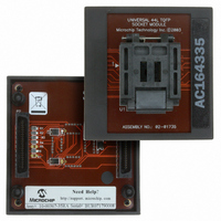
Manufacturer Part Number
AC164335
Description
MODULE SKT FOR 10X10 PM3 44TQFP
Manufacturer
Microchip Technology
Datasheet
1.AC164335.pdf
(286 pages)
Specifications of AC164335
Module/board Type
Socket Module - TQFP
Product
Microcontroller Accessories
Lead Free Status / RoHS Status
Not applicable / Not applicable
For Use With/related Products
MPLAB® PM3
For Use With
DV007003 - PROGRAMMER UNIVERSAL PROMATE II
Lead Free Status / RoHS Status
Lead free / RoHS Compliant, Not applicable / Not applicable


All byte loads into any W register are loaded into the
LSB. The MSB is not modified.
A Sign-Extend (SE) instruction is provided to allow
users to translate 8-bit signed data to 16-bit signed
values. Alternatively, for 16-bit unsigned data, users
can clear the MSB of any W register by executing a
Zero-Extend (ZE) instruction on the appropriate
address.
Although most instructions are capable of operating on
word or byte data sizes, it should be noted that some
instructions, including the DSP instructions, operate
only on words.
3.2.5
An 8 Kbyte ‘near’ data space is reserved in X address
memory space between 0x0000 and 0x1FFF, which is
directly addressable via a 13-bit absolute address field
within all memory direct instructions. The remaining X
address space and all of the Y address space is
addressable indirectly. Additionally, the whole of X data
space is addressable using MOV instructions, which
support memory direct addressing with a 16-bit
address field.
3.2.6
The dsPIC DSC device contains a software stack. W15
is used as the Stack Pointer.
The Stack Pointer always points to the first available
free word and grows from lower addresses towards
higher addresses. It pre-decrements for stack pops and
post-increments for stack pushes, as shown in
Figure 3-9. Note that for a PC push during any CALL
instruction, the MSB of the PC is zero-extended before
the push, ensuring that the MSB is always clear.
There is a Stack Pointer Limit register (SPLIM) associ-
ated with the Stack Pointer. SPLIM is uninitialized at
Reset. As is the case for the Stack Pointer, SPLIM<0>
is forced to ‘0’, because all stack operations must be
word-aligned. Whenever an Effective Address (EA) is
© 2006 Microchip Technology Inc.
Note:
NEAR DATA SPACE
SOFTWARE STACK
A PC push during exception processing
will concatenate the SRL register to the
MSB of the PC prior to the push.
Preliminary
generated using W15 as a source or destination
pointer, the address thus generated is compared with
the value in SPLIM. If the contents of the Stack Pointer
(W15) and the SPLIM register are equal and a push
operation is performed, a stack error trap will not occur.
The stack error trap will occur on a subsequent push
operation. Thus, for example, if it is desirable to cause
a stack error trap when the stack grows beyond
address 0x2000 in RAM, initialize the SPLIM with the
value, 0x1FFE.
Similarly, a Stack Pointer Underflow (stack error) trap is
generated when the Stack Pointer address is found to
be less than 0x0800, thus preventing the stack from
interfering with the Special Function Register (SFR)
space.
A write to the SPLIM register should not be immediately
followed by an indirect read operation using W15.
FIGURE 3-9:
3.2.7
The dsPIC30F1010/202X devices support data RAM
protection features which enable segments of RAM to
be protected when used in conjunction with Boot Code
Segment Security. BSRAM (Secure RAM segment for
BS) is accessible only from the Boot Segment Flash
code when enabled. See Table 3-3 for the BSRAM
SFR.
dsPIC30F1010/202X
0x0000
000000000
15
DATA RAM PROTECTION
<Free Word>
PC<15:0>
PC<22:16>
CALL STACK FRAME
0
W15 (before CALL)
W15 (after CALL)
PUSH: [W15++]
POP: [--W15]
DS70178C-page 37
Related parts for AC164335
Image
Part Number
Description
Manufacturer
Datasheet
Request
R

Part Number:
Description:
Manufacturer:
Microchip Technology Inc.
Datasheet:
Part Number:
Description:
Manufacturer:
Microchip Technology Inc.
Datasheet:
Part Number:
Description:
Manufacturer:
Microchip Technology Inc.
Datasheet:
Part Number:
Description:
Manufacturer:
Microchip Technology Inc.
Datasheet:
Part Number:
Description:
Manufacturer:
Microchip Technology Inc.
Datasheet:
Part Number:
Description:
Manufacturer:
Microchip Technology Inc.
Datasheet:
Part Number:
Description:
Manufacturer:
Microchip Technology Inc.
Datasheet:
Part Number:
Description:
Manufacturer:
Microchip Technology Inc.
Datasheet: