AC164336 Microchip Technology, AC164336 Datasheet - Page 100
AC164336
Manufacturer Part Number
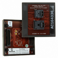
AC164336
Description
MODULE SOCKET FOR PM3 28/44QFN
Manufacturer
Microchip Technology
Datasheet
1.AC164335.pdf
(286 pages)
Specifications of AC164336
Module/board Type
Socket Module - QFN
Product
Microcontroller Accessories
Lead Free Status / RoHS Status
Not applicable / Not applicable
For Use With/related Products
MPLAB® PM3
Lead Free Status / RoHS Status
Lead free / RoHS Compliant, Not applicable / Not applicable


dsPIC30F1010/202X
10.1
The simple capture events in the dsPIC30F product
family are:
• Capture every falling edge
• Capture every rising edge
• Capture every 4th rising edge
• Capture every 16th rising edge
• Capture every rising and falling edge
These simple Input Capture modes are configured by
setting the appropriate bits ICM<2:0> (ICxCON<2:0>).
10.1.1
There are four input capture prescaler settings, speci-
fied by bits ICM<2:0> (ICxCON<2:0>). Whenever the
capture channel is turned off, the prescaler counter will
be cleared. In addition, any Reset will clear the
prescaler counter.
10.1.2
Each capture channel has an associated FIFO buffer,
which is four 16-bit words deep. There are two status
flags, which provide status on the FIFO buffer:
• ICBFNE – Input Capture Buffer Not Empty
• ICOV – Input Capture Overflow
The ICBFNE will be set on the first input capture event
and remain set until all capture events have been read
from the FIFO. As each word is read from the FIFO, the
remaining words are advanced by one position within
the buffer.
In the event that the FIFO is full with four capture
events and a fifth capture event occurs prior to a read
of the FIFO, an Overflow condition will occur and the
ICOV bit will be set to a logic ‘1’. The fifth capture event
is lost and is not stored in the FIFO. No additional
events will be captured until all four events have been
read from the buffer.
If a FIFO read is performed after the last read and no
new capture event has been received, the read will
yield indeterminate results.
DS70178C-page 98
Simple Capture Event Mode
CAPTURE PRESCALER
CAPTURE BUFFER OPERATION
Preliminary
10.1.3
The input capture module consists of up to 8 input cap-
ture channels. Each channel can select between one of
two timers for the time base, Timer2 or Timer3.
Selection of the timer resource is accomplished
through SFR bit ICTMR (ICxCON<7>). Timer3 is the
default timer resource available for the input capture
module.
10.1.4
When the input capture module is set for capture on
every edge, rising and falling, ICM<2:0> = 001, the fol-
lowing operations are performed by the input capture
logic:
• The input capture interrupt flag is set on every
• The Interrupt on Capture mode setting bits,
• A Capture Overflow condition is not generated in
edge, rising and falling.
ICI<1:0>, are ignored, since every capture
generates an interrupt.
this mode.
TIMER2 AND TIMER3 SELECTION
MODE
HALL SENSOR MODE
© 2006 Microchip Technology Inc.
Related parts for AC164336
Image
Part Number
Description
Manufacturer
Datasheet
Request
R

Part Number:
Description:
Manufacturer:
Microchip Technology Inc.
Datasheet:
Part Number:
Description:
Manufacturer:
Microchip Technology Inc.
Datasheet:
Part Number:
Description:
Manufacturer:
Microchip Technology Inc.
Datasheet:
Part Number:
Description:
Manufacturer:
Microchip Technology Inc.
Datasheet:
Part Number:
Description:
Manufacturer:
Microchip Technology Inc.
Datasheet:
Part Number:
Description:
Manufacturer:
Microchip Technology Inc.
Datasheet:
Part Number:
Description:
Manufacturer:
Microchip Technology Inc.
Datasheet:
Part Number:
Description:
Manufacturer:
Microchip Technology Inc.
Datasheet: