AC164336 Microchip Technology, AC164336 Datasheet - Page 137
AC164336
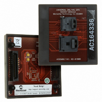
Manufacturer Part Number
AC164336
Description
MODULE SOCKET FOR PM3 28/44QFN
Manufacturer
Microchip Technology
Datasheet
1.AC164335.pdf
(286 pages)
Specifications of AC164336
Module/board Type
Socket Module - QFN
Product
Microcontroller Accessories
Lead Free Status / RoHS Status
Not applicable / Not applicable
For Use With/related Products
MPLAB® PM3
Lead Free Status / RoHS Status
Lead free / RoHS Compliant, Not applicable / Not applicable


12.25 Simultaneous PWM Faults and
The current-limit override function, if enabled and
active, forces the PWMxH,L pins to the values speci-
fied by the CLDAT<1:0> bits in the IOCONx registers
UNLESS the Fault function is enabled and active. If the
selected Fault input is active, the PWMxH,L outputs
assume the values specified by the FLTDAT<1:0> bits
in the IOCONx registers.
12.26 PWM Fault and Current-Limit TRG
The Fault and current-limit source selection fields in the
FCLCONx registers (FLTSRC<3:0> and CLSRC<3:0>)
control multiplexers in each PWM generator module.
The control multiplexers select the desired Fault and
current-limit signals for their respective modules. The
selected Fault and current-limit signals are also avail-
able to the ADC module as trigger signals that initiate
ADC sampling and conversion operations.
12.27 PWM Output Override Priority
If the PWM module is enabled, the priority of PWMx pin
ownership is:
1.
2.
3.
4.
5.
If the PWM module is disabled, the GPIO module
controls the PWMx pins.
12.28 Fault and Current-Limit Override
The PWMxH and PWMxL outputs are immediately
driven
CLDAT<1:0> and the FLTDAT<1:0> bits when a
current-limit or a Fault event occurs.
The override data is gated with the PWM signals going
into the dead-time logic block, and at the output of the
PWM module, just ahead of the PWM pin output
buffers.
Many applications require fast response to current
shutdown for accurate current control and/or to limit
circuitry damage to Fault currents.
Some applications will set the complementary
PWM outputs high in synchronous rectifier
designs when a Fault or current-limit event
occurs. If the CLDAT or FLTDAT bits are set to ‘1’,
and their associated event occurs, then these
asserted outputs will be delayed by clocked logic
in the dead-time circuitry.
© 2006 Microchip Technology Inc.
PWM Generator (lowest priority)
Output Override
Current-Limit Override
Fault Override
PENx (GPIO/PWM) ownership (highest priority)
low
Current Limits
Outputs To ADC
Issues with Dead-Time Logic
(deasserted)
as
specified
by
Preliminary
the
12.29 Asserting Outputs via Current
It is possible to use the CLDAT bits to assert the
PWMxH,L outputs in response to a current-limit event.
Such behavior could be used as a current “force” fea-
ture in response to an external current or voltage mea-
surement that indicates a sudden sharp increase in the
load on the power-converter output. Forcing the PWM
“ON” could be viewed as a “Feed-Forward” term that
allows quick system response to unexpected load
increases without waiting for the digital control loop to
respond.
12.30 PWM Immediate Update
For high-performance PWM control-loop applications,
the user may want to force the duty cycle updates to
occur immediately. Setting the IUE bit in the
PWMCONx register enables this feature.
In a closed-loop control application, any delay between
the sensing of a system’s state and the subsequent
outputting of PWM control signals that drive the appli-
cation reduces the loop stability. Setting the IUE bit
minimizes the delay between writing the duty cycle reg-
isters and the response of the PWM generators to that
change.
12.31 PWM Output Override
All control bits associated with the PWM output
override function are contained in the IOCONx register.
If the PENH, PENL bits are set, the PWM module
controls the PWMx output pins.
The PWM output override bits allow the user to manu-
ally drive the PWM I/O pins to specified logic states
independent of the duty cycle comparison units.
The OVRDAT<1:0> bits in the IOCONx register deter-
mine the state of the PWM I/O pins when a particular
output is overridden via the OVRENH,L bits.
The OVRENH, OVRENL bits are active high control
bits. When the OVREN bits are set, the corresponding
OVRDAT bit overrides the PWM output from the PWM
generator.
12.31.1
When the PWM is in Complementary Output mode, the
dead-time generator is still active with overrides. The
output overrides and Fault overrides generate control
signals used by the dead-time unit to set the outputs as
requested, including dead time.
Dead-time insertion can be performed when PWM
channels are overridden manually.
dsPIC30F1010/202X
Limit
COMPLEMENTARY OUTPUT MODE
DS70178C-page 135
Related parts for AC164336
Image
Part Number
Description
Manufacturer
Datasheet
Request
R

Part Number:
Description:
Manufacturer:
Microchip Technology Inc.
Datasheet:
Part Number:
Description:
Manufacturer:
Microchip Technology Inc.
Datasheet:
Part Number:
Description:
Manufacturer:
Microchip Technology Inc.
Datasheet:
Part Number:
Description:
Manufacturer:
Microchip Technology Inc.
Datasheet:
Part Number:
Description:
Manufacturer:
Microchip Technology Inc.
Datasheet:
Part Number:
Description:
Manufacturer:
Microchip Technology Inc.
Datasheet:
Part Number:
Description:
Manufacturer:
Microchip Technology Inc.
Datasheet:
Part Number:
Description:
Manufacturer:
Microchip Technology Inc.
Datasheet: