AT90USBKEY2 Atmel, AT90USBKEY2 Datasheet - Page 8
AT90USBKEY2
Manufacturer Part Number
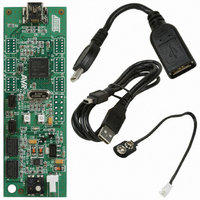
AT90USBKEY2
Description
KIT DEMO FOR AT90USB
Manufacturer
Atmel
Specifications of AT90USBKEY2
Main Purpose
USB Controller
Embedded
*
Utilized Ic / Part
AT90USB1286, AT90USB1287, AT90USB646, AT90USB647
Primary Attributes
*
Secondary Attributes
*
Supplier
Atmel
Architecture
8/16-bit
Interfaces
USB
For Use With
ATSTK525 - KIT STARTER FOR AT90USB
Lead Free Status / RoHS Status
Lead free / RoHS Compliant
Other names
AT90USBKEY
AT90USBKEY
AT90USBKEY


7627A–AVR–04/06
Using the AT90USBKey
2.3
2.3.1
2.3.2
2.3.3
2-8
Reset
Power-on RESET
RESET Push Button
Main Clock XTAL
Although the AT90USB has its on-chip RESET circuitry (c.f. AT90USB Datasheet,
section “System Control and Reset), the AVRUSBKey provides to the AT90USB a
RESET signal witch can come from two different sources:
Figure 2-4 . Reset Implementation
The on-board RC network acts as power-on RESET.
By pressing the RESET push button on the AVRUSBKey, a warm RESET of the
AT90USB is performed.
To use the USB interface of the AT90USB, the clock source should always be a crystal
or external clock oscillator (the internal 8MHz RC oscillator can not be used to operate
with the USB interface). Only the following crystal frequency allows proper USB
operations: 2MHz, 4MHz, 6MHz, 8MHz, 12MHz, 16MHz. The AT90USBKey comes with
a default 8MHz crystal oscillator.
RST
VCC
R6
47k
220nF
C8
AT90USBKey Hardware User Guide
RESET
Related parts for AT90USBKEY2
Image
Part Number
Description
Manufacturer
Datasheet
Request
R

Part Number:
Description:
MCU, MPU & DSP Development Tools Demo board f/AVR MCU & AT90USB
Manufacturer:
Atmel
Datasheet:

Part Number:
Description:
Digital Attenuator 32-Pin FQFP T/R
Manufacturer:
M/A-Com Technology Solutions
Datasheet:
Part Number:
Description:
MLP DIGITAL ATTENUATOR
Manufacturer:
M/A-Com Technology Solutions
Part Number:
Description:
Digital Attenuator 32-Pin FQFP
Manufacturer:
M/A-Com Technology Solutions
Datasheet:
Part Number:
Description:
Digital Attenuator 32-Pin FQFP T/R
Manufacturer:
M/A-Com Technology Solutions
Datasheet:
Part Number:
Description:
MLP DIGITAL ATTENUATOR
Manufacturer:
M/A-Com Technology Solutions

Part Number:
Description:
Digital Attenuator, 50 Db, 6-bit, Ttl Driver, Dc-2.4 Ghz
Manufacturer:
Tyco Electronics
Datasheet:
Part Number:
Description:
Digital Attenuator, 31.5 Db, 6-bit, Ttl Driver, Dc-4.0 Ghz
Manufacturer:
Tyco Electronics
Datasheet:
Part Number:
Description:
Digital Attenuator, 31.5 Db, 6-bit, Ttl Driver, Dc-4.0 Ghz
Manufacturer:
Tyco Electronics
Datasheet:
Part Number:
Description:
Digital Attenuator, 31db, 5-bit, Ttl Driver Dc - 3.0 Ghz
Manufacturer:
Tyco Electronics
Datasheet:

Part Number:
Description:
INTERVAL AND WIPE/WASH WIPER CONTROL IC WITH DELAY
Manufacturer:
ATMEL Corporation
Datasheet:
Part Number:
Description:
Low-Voltage Voice-Switched IC for Hands-Free Operation
Manufacturer:
ATMEL Corporation
Datasheet:
Part Number:
Description:
MONOLITHIC INTEGRATED FEATUREPHONE CIRCUIT
Manufacturer:
ATMEL Corporation
Datasheet:
Part Number:
Description:
AM-FM Receiver IC U4255BM-M
Manufacturer:
ATMEL Corporation
Datasheet: