UM245R FTDI, Future Technology Devices International Ltd, UM245R Datasheet - Page 21
UM245R
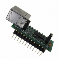
Manufacturer Part Number
UM245R
Description
MODULE USB-PAR FIFO TTL 24-DIP
Manufacturer
FTDI, Future Technology Devices International Ltd
Datasheet
1.UM245R.pdf
(27 pages)
Specifications of UM245R
Main Purpose
Interface, USB 2.0 to Parallel FIFO Bridge
Embedded
No
Utilized Ic / Part
FT245R
Primary Attributes
300kBps to 1MBps USB to parallel FIFO via 4-Wire Interface
Secondary Attributes
Royalty-Free Drivers
Lead Free Status / RoHS Status
Lead free / RoHS Compliant
Other names
768-1020


7.3 USB Bus Powered with Power Switching Confiduration
Figure 7.3 Bus Powered with Power Switching Configuration
USB Bus powered circuits need to be able to power down in USB suspend mode in order to meet the <=
500μA (2.5mA with remote wake-up enabled) total USB suspend current requirement, including external
logic. Some external logic can power itself down into a low current state by monitoring the PWREN#
signal. For external logic that cannot power itself down in this way, the FT245R provides a simple but
effective way of turning off power to external circuitry during USB suspend.
Figure 7.3 shows how to use a discrete P-Channel Logic Level MOSFET to control the power to external
logic circuits. A suitable device would be an International Rectifier (www.irf.com) IRLML6402, or
equivalent. It is recommended that a “soft start” circuit consisting of a 1kΩ series resistor and a 0.1μF
capacitor are used to limit the current surge when the MOSFET turns on. Without the soft start circuit
there is a danger that the transient power surge of the MOSFET turning on will reset the FT245R, or the
USB host / hub controller. The values used here allow attached circuitry to power up with a slew rate of
~12.5V per millisecond, in other words the output voltage will transition from GND to 5V in
approximately 400 microseconds.
Alternatively, a dedicated power switch I.C. with inbuilt “soft-start” can be used instead of a MOSFET. A
suitable power switch I.C. for such an application would be a Micrel (www.micrel.com) MIC2025-2BM or
equivalent.
Please note the following points in connection with power controlled designs:
© Copyright 2009 Future Technology Devices International Ltd
i)
ii) Set the Pull-down on Suspend option in the internal EEPROM.
iii) The PWE# pin should be used to switch the power to the external circuitry.
iv) For USB high-power bus powered device (one that consumes greater than 100mA, and up to
v) For 3.3V power controlled circuits the VCCIO pin must not be powered down with the external
The logic to be controlled must have its own reset circuitry so that it will automatically reset itself
when power is re-applied on coming out of suspend.
500mA of current from the USB bus), the power consumption of the device should be set in
the max power field in the internal EEPROM. A high-power bus powered device must use this
descriptor in the internal EEPROM to inform the system of its power requirements.
circuitry (the PWREN# signal gets its supply from VCCIO). Either connect the power switch
between the output of the 3.3V regulator and the external 3.3V logic or power VCCIO from
the 3V3OUT pin of the FT245R.
UM245R USB - Parallel FIFO Development Module Datasheet Version 1.04
Document Reference No.: FT_000202
Clearance No.: FTDI# 124
20
Related parts for UM245R
Image
Part Number
Description
Manufacturer
Datasheet
Request
R

Part Number:
Description:
IC USB TO SERIAL UART 32-QFN
Manufacturer:
FTDI, Future Technology Devices International Ltd

Part Number:
Description:
IC USB HOST CTLR VINCULUM 48LQFP
Manufacturer:
FTDI, Future Technology Devices International Ltd
Datasheet:

Part Number:
Description:
IC USB HOST VINCULUM-II 32QFN
Manufacturer:
FTDI, Future Technology Devices International Ltd
Datasheet:
Part Number:
Description:
IC USB HOST VINCULUM-II 32LQFN
Manufacturer:
FTDI, Future Technology Devices International Ltd
Datasheet:
Part Number:
Description:
IC USB HOST VINCULUM-II 48QFN
Manufacturer:
FTDI, Future Technology Devices International Ltd
Datasheet:
Part Number:
Description:
IC USB HOST VINCULUM-II 32LQFN
Manufacturer:
FTDI, Future Technology Devices International Ltd
Datasheet:
Part Number:
Description:
IC USB HOST VINCULUM-II 32QFN
Manufacturer:
FTDI, Future Technology Devices International Ltd
Datasheet:
Part Number:
Description:
IC USB HOST VINCULUM-II 48LQFP
Manufacturer:
FTDI, Future Technology Devices International Ltd
Datasheet:
Part Number:
Description:
IC USB HOST VINCULUM-II 48LQFP
Manufacturer:
FTDI, Future Technology Devices International Ltd
Datasheet:
Part Number:
Description:
IC USB HOST VINCULUM-II 48QFN
Manufacturer:
FTDI, Future Technology Devices International Ltd
Datasheet:
Part Number:
Description:
IC USB HOST CTLR VINCULUM 64QFN
Manufacturer:
FTDI, Future Technology Devices International Ltd
Datasheet:

Part Number:
Description:
IC USB HOST CTLR VINCULUM 64LQFP
Manufacturer:
FTDI, Future Technology Devices International Ltd
Datasheet:
Part Number:
Description:
IC USB HOST VINCULUM-II 64LQFP
Manufacturer:
FTDI, Future Technology Devices International Ltd
Datasheet:
Part Number:
Description:
IC USB HOST VINCULUM-II 64QFN
Manufacturer:
FTDI, Future Technology Devices International Ltd
Datasheet:

Part Number:
Description:
IC USB TO PARALLEL FIFO 28-SSOP
Manufacturer:
FTDI, Future Technology Devices International Ltd
Datasheet: