MCP2515DM-PCTL Microchip Technology, MCP2515DM-PCTL Datasheet
MCP2515DM-PCTL
Specifications of MCP2515DM-PCTL


Related parts for MCP2515DM-PCTL


MCP2515DM-PCTL Summary of contents
Page 1
... CAN Controller PICtail™ Demo Board User’s Guide © 2005 Microchip Technology Inc. MCP2515 Stand-Alone DS51572A ...
Page 2
... PowerMate, PowerTool, rfLAB, rfPICDEM, Select Mode, Smart Serial, SmartTel, Total Endurance and WiperLock are trademarks of Microchip Technology Incorporated in the U.S.A. and other countries. SQTP is a service mark of Microchip Technology Incorporated in the U.S.A. All other trademarks mentioned herein are property of their respective companies. ...
Page 3
... Introduction ..................................................................................................... 7 2.2 Features ......................................................................................................... 7 2.3 Getting Started ............................................................................................... 8 2.4 Firmware Description ..................................................................................... 8 Appendix A. Schematics and Layouts ...................................................................... 11 A.1 Introduction .................................................................................................. 11 Appendix B. Bill of Materials (BOM) .......................................................................... 15 Worldwide Sales and Service .................................................................................... 16 © 2004 Microchip Technology Inc. MCP2515 PICtail™ DEMO BOARD USER’S GUIDE Table of Contents DS51572A-page iii ...
Page 4
... MCP2515 PICtail™ Demo Board User’s Guide NOTES: DS51572A-page iv © 2004 Microchip Technology Inc. ...
Page 5
... Appendix A. “Schematics and Layouts” – Shows the schematic and layout diagrams for the MCP2515 PICtail™ Demo Board. • Appendix B. “Bill of Materials (BOM)” – Lists the parts used to build the MCP2515 PICtail™ Demo Board. © 2005 Microchip Technology Inc. DEMO BOARD USER’S GUIDE Preface NOTICE TO CUSTOMERS MCP2515 PICtail™ ...
Page 6
... MPLAB IDE User’s Guide ...is the only compiler... the Output window the Settings dialog select Enable Programmer “Save project before build” File>Save Click OK Click the Power tab 4‘b0010, 2‘hF1 Press <Enter>, <F1> Literature # DS21664 © 2005 Microchip Technology Inc. ...
Page 7
... Local sales offices are also available to help customers. A listing of sales offices and locations is included in the back of this document. Technical support is available through the web site at: http://support.microchip.com DOCUMENT REVISION HISTORY Revision A (August 2005) • Initial release of this document. © 2005 Microchip Technology Inc. Preface DS51572A-page 3 ...
Page 8
... MCP2515 PICtail NOTES: DS51572A-page 4 Demo Board User’s Guide © 2005 Microchip Technology Inc. ...
Page 9
... MCP2502X/5X Data Sheet (DS21664) (electronic version on CD) • MCP2551 Data Sheet (DS21667) (electronic version on CD) • MCP2515 PICtail™ Demo Board User’s Guide (DS21572) (electronic version on CD) © 2005 Microchip Technology Inc. MCP2515 PICtail™ DEMO BOARD USER’S GUIDE DS51572A-page 5 ...
Page 10
... MCP2515 PICtail NOTES: DS51572A-page 6 Demo Board User’s Guide © 2005 Microchip Technology Inc. ...
Page 11
... Two headers on Node A, used for programming the PICmicro Unit (MCU) using the programming features of the PICkit™ 1 Flash Starter Kit or PICkit™ 2 Microcontroller Programmer. Neither header is populated. Refer to Appendix A. “Schematics and Layouts”. © 2005 Microchip Technology Inc. MCP2515 PICtail™ DEMO BOARD USER’S GUIDE ® ...
Page 12
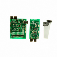
... User’s Guide (DS51553) for more information on programming PICmicro MCUs. FIGURE 2-1: Node B DS51572A-page 8 Demo Board User’s Guide ® MCU. Refer to the PICkit™ 2 Microcontroller Programmer SETUP CONFIGURATION Perforation Node A MCP2515 PICtail™ Eval Bd. and GND test points, or plug Adapter © 2005 Microchip Technology Inc. ...
Page 13
... The firmware checks a global receive flag bit to determine if a message has been received by the MCP2515. If yes, the data is read and the LED is set accordingly. 4. The firmware loops back to #2. FIGURE 2-2: © 2005 Microchip Technology Inc. Installation and Operation FIRMWARE FLOW DIAGRAM Start ...
Page 14
... I/O status (i.e., push button status) from SendMsg TXB1 Clear gSampleFlag This flag is set in the ISR for the INT pin. gRXFlag? RXMsg LED Status? OFF ON (gLEDStatus) Clear gRXFlag A A TX0D3<4> (TX0D3 = 0x10) LED = OFF Node B (MCP25020 RC2 = 1 ServiceIO © 2005 Microchip Technology Inc. ...
Page 15
... This appendix contains the schematic and PCB layout for the MCP2515 PICtail™ Demo Board. Diagrams included: • Board Schematic – Sheet • Board Schematic – Sheet • Board – Top Layer (with silk-screen) • Board – Bottom Layer © 2005 Microchip Technology Inc. MCP2515 PICtail™ DEMO BOARD USER’S GUIDE DS51572A-page 11 ...
Page 16
... MCP2515 PICtail FIGURE A-1: BOARD SCHEMATIC – SHEET DS51572A-page 12 Demo Board User’s Guide © 2005 Microchip Technology Inc. ...
Page 17
... FIGURE A-2: BOARD SCHEMATIC – SHEET © 2005 Microchip Technology Inc. Schematics and Layouts DS51572A-page 13 ...
Page 18
... MCP2515 PICtail FIGURE A-3: BOARD – TOP LAYER (WITH SILK-SCREEN) FIGURE A-4: BOARD – BOTTOM LAYER DS51572A-page 14 Demo Board User’s Guide © 2005 Microchip Technology Inc. ...
Page 19
... U3,U5 High-Speed CAN Transceiver 1 U4 CAN I/O Expander for a Controller Area Network (CAN) system, 1 Y1,Y2 Resonator 16.0 MHZ Ceramic © 2005 Microchip Technology Inc. DEMO BOARD USER’S GUIDE Description Manufacturer Panasonic ® Kemet Lite-On Trading USA Inc Keystone Electronics ® ...
Page 20
... Fax: 886-3-572-6459 Taiwan - Kaohsiung Tel: 886-7-536-4818 Fax: 886-7-536-4803 Taiwan - Taipei Tel: 886-2-2500-6610 Fax: 886-2-2508-0102 Thailand - Bangkok Tel: 66-2-694-1351 Fax: 66-2-694-1350 © 2005 Microchip Technology Inc. EUROPE Austria - Weis Tel: 43-7242-2244-399 Fax: 43-7242-2244-393 Denmark - Copenhagen Tel: 45-4450-2828 Fax: 45-4485-2829 France - Paris Tel: 33-1-69-53-63-20 ...