MCP2515DM-PCTL Microchip Technology, MCP2515DM-PCTL Datasheet - Page 11
MCP2515DM-PCTL
Manufacturer Part Number
MCP2515DM-PCTL
Description
BOARD DEMO FOR MCP2515
Manufacturer
Microchip Technology
Series
PICtail™r
Type
Network Controller & Processorr
Specifications of MCP2515DM-PCTL
Main Purpose
Interface, CAN Controller
Embedded
Yes, MCU, 8-Bit
Utilized Ic / Part
MCP2515, MCP25020
Primary Attributes
Stand alone CAN Controller with CAN I/O Expander
Interface Type
CAN
Operating Voltage
5 V
Product
Modules
For Use With/related Products
MCP2515, MCP25020
Lead Free Status / RoHS Status
Contains lead / RoHS non-compliant
Secondary Attributes
-
Lead Free Status / Rohs Status
Lead free / RoHS Compliant


2.1
2.2
© 2005 Microchip Technology Inc.
INTRODUCTION
FEATURES
Chapter 2. Installation and Operation
This chapter discusses the setup and operation of the MCP2515 PICtail™ Demo
Board.
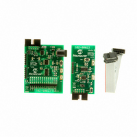
The MCP2515 PICtail™ Demo Board is designed to demonstrate the MCP2515 and
MCP25020 as simple, low-cost CAN nodes. Both nodes monitor an input push button
and send CAN messages with the button condition at regular intervals. The CAN
message is received by the other node, where a LED is set to mirror the button state.
The MCP2515 PICtail™ Demo Board has the following features:
• Two (2) CAN nodes consisting of:
• Each node also has one push button and one LED connected to the I/O.
• Two headers on Node A, used for programming the PICmicro
Unit (MCU) using the programming features of the PICkit™ 1 Flash Starter Kit or
PICkit™ 2 Microcontroller Programmer. Neither header is populated. Refer to
Appendix A. “Schematics and Layouts”.
- Node A: MCP2515, PIC16F676 and a MCP2551 CAN transceiver.
- Node B: MCP25020 CAN I/O Expander and MCP2551 CAN transceiver.
- The push button state from each node is sent to the other node via a CAN
message.
DEMO BOARD USER’S GUIDE
MCP2515 PICtail™
®
Microcontroller
DS51572A-page 7
Related parts for MCP2515DM-PCTL
Image
Part Number
Description
Manufacturer
Datasheet
Request
R

Part Number:
Description:
BOARD DAUGHTER PICTAIL MCP2515
Manufacturer:
Microchip Technology
Datasheet:

Part Number:
Description:
BOARD DEMO FOR MCP2515/51
Manufacturer:
Microchip Technology
Datasheet:

Part Number:
Description:
Manufacturer:
Microchip Technology Inc.
Datasheet:
Part Number:
Description:
Manufacturer:
Microchip Technology Inc.
Datasheet:
Part Number:
Description:
Manufacturer:
Microchip Technology Inc.
Datasheet:
Part Number:
Description:
Manufacturer:
Microchip Technology Inc.
Datasheet:
Part Number:
Description:
Manufacturer:
Microchip Technology Inc.
Datasheet:
Part Number:
Description:
Manufacturer:
Microchip Technology Inc.
Datasheet:
Part Number:
Description:
Manufacturer:
Microchip Technology Inc.
Datasheet:
Part Number:
Description:
Manufacturer:
Microchip Technology Inc.
Datasheet: