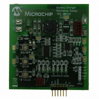
MCP1631RD-MCC2 Microchip Technology, MCP1631RD-MCC2 Datasheet

MCP1631RD-MCC2
Specifications of MCP1631RD-MCC2
Related parts for MCP1631RD-MCC2
MCP1631RD-MCC2 Summary of contents
Page 1
... This enables customers to choose between portability, runtime and cost when purchasing a portable system. © 2007 Microchip Technology Inc. Battery Chargers COMMON CHARGE PROFILES NiMH Charge Profile ...
Page 2
... DS01137A-page 2 NiMH and NiCd Charge Profile Stage 2 Stage 3 Fast Charge End Fast Charge V CELL I = 1.0C CH Pack T (°C) Stage 4 Top Off Charge -dV/dt -dT/dt 1 hour I = 0.05C CH © 2007 Microchip Technology Inc. ...
Page 3
... Any power dissipation over a few watts is a challenge to cool. Cooling 18 watts of power dissipation is no easy task, airflow and large heatsinks are required making a linear solution impractical. © 2007 Microchip Technology Inc. Li-Ion Charge Profile Stage 3 Stage 2 Constant Voltage Constant Current ...
Page 4
... V input to the MCP1631HV and to decrease current, the microcontroller decreases the V MCP1631HV. To generate a charge algorithm, the microcontroller measures the battery voltage using an Blocking Diode +Vbatt C OUT SENSE Batteries REF input to the REF © 2007 Microchip Technology Inc. ...
Page 5
... MCP1631 device option without internal regulator can be used. By using a high voltage regulator to bias the MCP1631 and microcontroller, the range of input voltage for the design is only limited by the regulator maximum input and power train design. © 2007 Microchip Technology Inc. AN1137 V = +5.3V to +16. ...
Page 6
... The V is set by the microcontroller to program the proper charge current. Latch High Speed Comparator pin VDD pin and VDD and V are REF FB input is high, the inverting FB input REF P VDD MOSFET P V EXT MOSFET N P GND © 2007 Microchip Technology Inc. ...
Page 7
... The OV protection is not there to protect the battery used to protect the power train from excessive voltage if the battery is © 2007 Microchip Technology Inc. MCP1631HV integrates an inverting 10V/V gain amplifier to increase the battery current sense signal. The microcontroller sets the V current level, the MCP1631HV uses the V a reference for regulation ...
Page 8
... AN1137 CS INPUT V REF + FIGURE 7: MCP1631HV Voltage Buffer and Overvoltage Comparator Setup. DS01137A-page 8 To PWM Latch H = PWM C1 VS_OUT to microcontroller A/D Converter C OUT BATT OFF COMP + +1.2V Comp © 2007 Microchip Technology Inc. ...
Page 9
... Note 1: For Shutdown control, amplifier A3 remains functional so battery voltage can be sensed during discharge phase. FIGURE 8: MCP1631HV Block Diagram. © 2007 Microchip Technology Inc. the quiescent current draw to a 4.4 µA typical, the +5V generated bias is available and A3 remain powered for Figure 7 battery monitoring and microcontroller power. ...
Page 10
... STATUS INDICATOR FIGURE 9: Charger Diagram. DS01137A-page 10 charger application. Multi-cell, Multi-Chemistry Charger SCHOTTKY C C DIODE L1A L1B EXT I LIMIT CS GND PROTECTION IN IN REF PROGRAMMAGLE LOW I SHUTDOWN CURRENT SOURCE Q REFERENCE DIS OUT R GP5 R THERM C OUT BATTERY I SENSE C A VDD_OUT © 2007 Microchip Technology Inc. ...
Page 11
... A K FIGURE 10: Detailed Schematic. © 2007 Microchip Technology Inc AN1137 DS01137A-page 11 ...
Page 12
... AN1137 FIGURE 11: Board Layout. DS01137A-page 12 © 2007 Microchip Technology Inc. ...
Page 13
... V ------------ 2 n © 2007 Microchip Technology Inc µH inductor looks like a 20 µH inductor (for ® coupled inductors only). Larger inductance reduces ripple current and operates in the continuous mode at lighter loads, an advantage over non-coupled inductor solutions ...
Page 14
... If it does reach zero, this transfer function is no longer true and there is another state added to the operation. DS01137A-page – ⎛ ⎞ × ------------ - ⎝ ⎠ OUT is large 1 /V OUT IN © 2007 Microchip Technology Inc. ...
Page 15
... Power Train Design tON tOFF FIGURE 12: SEPIC Converter Inductor, Switch and Diode Currents. © 2007 Microchip Technology Inc OUT OUT OUT tON tOFF tON tOFF AN1137 I CHARGE I CHARGE I CHARGE Sum of Winding Currents IOUT (Average OUT OUT IN I (AVERAGE) IN DS01137A-page 15 ...
Page 16
... OUT = 311 mA ON +1/2 x ΔI OUTAVG L(W2 -1/2 x ΔI OUTAVG L(W2 the current in IN OUT = W (ripple and average equal to the combination 2.82A (Average × ⎛ ⎞ × -------------------------------------- - = D ⎜ ⎟ 3 ⎝ ⎠ = 2.51A = Minimum, = 3.14A = Maximum © 2007 Microchip Technology Inc. 1 ...
Page 17
... As previously discussed, the W 1 current is equal to the average input current. Therefore, the worst case or maximum RMS current in the coupling capacitor will occur at maximum output power © 2007 Microchip Technology Inc for the and minimum input voltage. To estimate size for the OUT coupling capacitor, the capacitor derivative equation can be used ...
Page 18
... No code or execution time is necessary to regulate or protect the circuit. The microcontroller is used for programmability, establishing charge profile conditions and monitoring the circuit for fault conditions and taking the appropriate action, in the event of a specific fault. © 2007 Microchip Technology Inc. ...
Page 19
... PowerInfo, PowerMate, PowerTool, REAL ICE, rfLAB, Select Mode, Smart Serial, SmartTel, Total Endurance, UNI/O, WiperLock and ZENA are trademarks of Microchip Technology Incorporated in the U.S.A. and other countries. SQTP is a service mark of Microchip Technology Incorporated in the U.S.A. All other trademarks mentioned herein are property of their respective companies. ...
Page 20
... Fax: 886-3-572-6459 Taiwan - Kaohsiung Tel: 886-7-536-4818 Fax: 886-7-536-4803 Taiwan - Taipei Tel: 886-2-2500-6610 Fax: 886-2-2508-0102 Thailand - Bangkok Tel: 66-2-694-1351 Fax: 66-2-694-1350 © 2007 Microchip Technology Inc. EUROPE Austria - Wels Tel: 43-7242-2244-39 Fax: 43-7242-2244-393 Denmark - Copenhagen Tel: 45-4450-2828 Fax: 45-4485-2829 France - Paris Tel: 33-1-69-53-63-20 ...


