MCP6XXXDM-FLTR Microchip Technology, MCP6XXXDM-FLTR Datasheet - Page 31
MCP6XXXDM-FLTR
Manufacturer Part Number
MCP6XXXDM-FLTR
Description
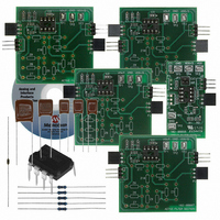
KIT DEMO BOARD ACTIVE FILTER
Manufacturer
Microchip Technology
Datasheet
1.MCP6XXXDM-FLTR.pdf
(46 pages)
Specifications of MCP6XXXDM-FLTR
Main Purpose
Filters, Active - Bandpass, Highpass, Lowpass
Embedded
Yes, MCU, 8-Bit
Utilized Ic / Part
MCP6271
Primary Attributes
Cascadable PCBs, Single Supply
Secondary Attributes
Bessel, Butterworth, and Chebyshev, with Order 1 ~ 8
Processor To Be Evaluated
MCP6271
Lead Free Status / RoHS Status
Not applicable / Not applicable
Lead Free Status / RoHS Status
Lead free / RoHS Compliant, Not applicable / Not applicable
Available stocks
Company
Part Number
Manufacturer
Quantity
Price
Company:

Part Number:
MCP6XXXDM-FLTR
Manufacturer:
MICROCHIP
Quantity:
12 000
Part Number:
MCP6XXXDM-FLTR
Manufacturer:
MICROCHIP/微芯
Quantity:
20 000


4.3
4.4
4.5
© 2006 Microchip Technology Inc.
FILTER SECTION ORDERING FOR NOISE AND HEADROOM
COMBINING LOW-PASS AND HIGH-PASS SECTIONS
HIGHER FREQUENCY FILTERS
FilterLab V2.0 orders the filter sections for good dynamic range performance. Its
default selections are:
• Section pole quality factors (Q
• Gains greater than unity are placed in Section # 1 (for best component
Some applications may need to alter the default section ordering for special
requirements. To compare different section orderings:
• Check the output headroom of each section’s output (V
• Measure the noise performance
• Re-connect the sections in a different order
Some band-pass and band reject filters can be implemented using cascaded low-pass
and high-pass filter sections. These filters have their pass-band frequencies (f
f
designed separately, then cascaded together.
The Active Filter Demo Board Kit allows the user to try out these filters on the bench
with little effort. They also help debug this type of design.
Higher frequency filters (e.g., a low-pass filter with pass band edge at 1 MHz) can have
their design initially verified on these boards. Simply scale either the resistors or capac-
itors to a lower frequency design:
• Increase resistors (or capacitors) by a power of 10
• Choose an op amp that is slower by the same power of 10
• Evaluate response:
For example, a low-pass filter with a pass-bandfrequency of 1 MHz could be scaled
back to 10 kHz.
The final design must be evaluated on a board capable of supporting higher frequency
signals.
PH
Section # 1 to Section # 4)
- In other words, section damping factors (ζ = 0.5/Q
sensitivities)
input signal; examples include:
- Minimum and maximum DC levels
- Swept frequency sine wave with maximum magnitude
- Voltage step with maximum step size
- Measure the output with a DC input signal (i.e., at mid-supply), an
- Calculate the standard deviation of the output; this is the integrated noise in
- The noise can be improved by scaling the resistors, or by changing the op
- Usually it is best to leave the high gain section at the front of the filter
- Re-check output headroom and noise
- All frequency parameters are divided by the same power of 10
- All time parameters are multiplied by the same power of 10
) far apart (e.g., f
(from Section # 1 to Section # 4)
oscilloscope, and a high gain low noise amplifier
V
amps
RMS
PH
/f
PL
> 5.8). The low-pass and high-pass filters are usually
P
) are ordered from lowest to highest (from
P
) go from highest to lowest
OUT
) using the worst-case
DS51614A-page 27
PL
and
Related parts for MCP6XXXDM-FLTR
Image
Part Number
Description
Manufacturer
Datasheet
Request
R

Part Number:
Description:
Manufacturer:
Microchip Technology Inc.
Datasheet:
Part Number:
Description:
Manufacturer:
Microchip Technology Inc.
Datasheet:
Part Number:
Description:
Manufacturer:
Microchip Technology Inc.
Datasheet:
Part Number:
Description:
Manufacturer:
Microchip Technology Inc.
Datasheet:
Part Number:
Description:
Manufacturer:
Microchip Technology Inc.
Datasheet:
Part Number:
Description:
Manufacturer:
Microchip Technology Inc.
Datasheet:
Part Number:
Description:
Manufacturer:
Microchip Technology Inc.
Datasheet:
Part Number:
Description:
Manufacturer:
Microchip Technology Inc.
Datasheet: